A GPS tracker is one of the most simple and interesting projects in the field of electronics, and for one of our projects we needed to track the position of a vehicle, so we started looking for circuits on the internet and were very surprised to find out that there were not a lot of modules available online that can do both GSM and GPS at the same time. On top of that, the majority of the projects available are based on SIM900L and NEO6M-based modules that are good for any general-purpose projects, but we needed something compact for our project to work. The solution to this problem is an A9G GSM/GPS module, that can do both GSM and GPS in a small compact module. So, in this tutorial, we decided to take a deep dive into the technical specs of this module and find out all its hidden features. Also, we will be building an SMS-based GPS tracker that will be able to update the position of the device with an SMS containing all the GPS location data.
In our previous article, we built an IoT Based GPS Location Tracker using NodeMCU and GPS Module and an Arduino-based Vehicle Tracker using GPS and GSM module. You can check all the GPS based projects and GSM based projects by following the links.
A9G-based Pudding Board's Features
The A9G-based pudding board comes with various features, most of the features that this board provides are based on the AG9 Chip itself, but there are other features that specifically the pudding board provides, and in this section of the article we will discuss all those features.
A9G Module

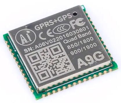
A9G is a complete quad-band GSM/GPRS+GPS module based on the RDA8955 chip. The Low BOM design of this module provides a cost-effective solution for modern IoT-based applications. Like any other GPRS module, this module also features call and SMS functionalities. Other than that, this module features a low-power mode with a minimum sleep current of 2mA other than that, it also provides firmware updates via the UART port.
A9G-based Pudding Board

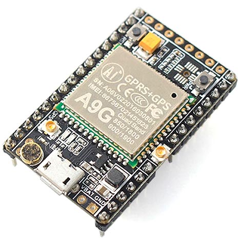
As you can read from the above description, the A9G module packs a ton of features but there are some important features that this module lags, so to close those loopholes the developers of the pudding board did a great job and designed a cool little board.
Additionally, they have added a placeholder for a battery connector so that you can power the board from a battery, and onboard there is a battery charger circuit that will charge the battery if power is applied through the USB or the 5V and GND pin of the board. Other than that, on the backside of the board, there is a sim holder and an SD card holder, so that you can store GPS data on an SD card module.
Components required for Vehicle Tracking System
To build an A9G-based vehicle tracking system, you don't need that many components. You only need a few components that are required to build this Arduino GPS tracker.
![]()
- Arduino Pro mini
- FTDI USB to serial Converter.
- A9G GSM/GPS module
- Battery Holder
- 18650 Lithium Battery
- Perfboard
- Connecting Wire
- Female Header
- Sun-board for enclosure
A9G-based GPS tracker Circuit Diagram
The schematic diagram of the A9G-based GPS tracker is simple. The A9G module supports AT command set. To control the A9G module, you just need to power the board with 5V and you need to connect the TX and RX pin of the Arduino to the RX and TX pin of the A9G module. That's all the connection you need to do to work with this module. Additionally, we are using a battery to power the module so the battery is in the schematic, the objective of the project is to test all the features of the A9G module so we did not add any additional circuitry to it, but you can add power or an accelerometer to improve the functionality of the circuit. This is a very versatile module and by slightly modifying it you can build a GPS tracker for a car, a GPS tracker for a bike, or even a GPS locator for travel-related activities.
![]()
Useful AT Command List for A9G GSM/GPS Module
If you are using the A9G GSM and GPS module for the first time. You must need the AT command list to check out all the functionalities that the module can do. Some useful AT commands are listed below.
AT+CREG?: check if you are registered to a network. If 1 then OK, otherwise you have a problem.
AT+CCID: shows the information about the CCID number.
AT+CSQ: shows the GSM/GPRS signal strengths.
AT+GPS = 1: Turns the GPS ON.
AT+GPS = 0: Turns the GPS OFF.
AT+GPSRD=1: Starts printing GPS Data to the serial monitor.
AT+GPSRD=0: Stops printing GPS Data to the serial monitor.
AT+LOCATION=1: This command is used to get location data through the LBS server.
AT+GPSUPGRADE: Release GPS UART from A9’s CPU, then you can connect GPS UART directly to communicate with GPS.
AT+CIPSTATUS: checks if IP is connected or not.
AT+CGDCONT=1: connects to the internet. Eg. AT+CGDCONT=1, "IP", "www".
AT+HTTPGET: use HTTPGET to receive data from the server.
AT+HTTPPOST: use POST method to post data to the server.
Useful Call Commands
ATA: Answer an Incoming Call.
ATD: Dial a number. To dial a number send an ATD+number.
ATH: Used to disconnect an incoming or outgoing call.
AT+SNFS=0: This command is used to enable onboard earphones and headphones. When it's set to 0 it's in headphone or earphone mode. When it's set to 1 it's in Loudspeaker Mode.
Useful SMS Commands
AT+CMGF=1: This command is used to set the message format if it's set to 1 then it's in text format, if it's set to 0 then it's in hex format.
AT+CMGS: this command is used to send messages to a given number. Example AT+CMGS = “+919804049270”. Upon hitting enter you will get > as response, now type your message and write(0x1A) to send an SMS with Arduino.
AT+CMGL: This command is used to read SMS from the storage of the module.
Arduino Code for A9G GSM GPS Module
The code to interface the A9G GSM/GPS module with Arduino is very simple and easy to understand, but before we start we need to download and install TinyGPSPlus.h library by mikalhart, and you will also be needing the software serial library which is built in the library of the Arduino.
We start our code by including all the required libraries and defining all the required variables for the code. First, we include the TinyGPSPlus library and SoftwareSerial library. Then we defined the RXPin and TXPin in which we connected our A9G module. Next, we have defined a string variable in which we have stored the permalink of google maps.
#include <TinyGPSPlus.h>
#include <SoftwareSerial.h>
static const int RXPin = 6, TXPin = 5;
String s = "www.google.com/maps/dir/";
Next, we have some other variables that will be used later in the code. The Interval and the previousMillis will be used in a section of code where we have called a function repeatedly after a certain period. The GPSBaud is used to set the baud rate of the SoftwareSerial of the Arduino. Finally, we have the data_counter variable, our objective in the code is to get 10 data points from the GPS and send it through SMS so the data_counter variable is used.
unsigned long interval = 10000;
static const uint32_t GPSBaud = 9600;
unsigned long previousMillis = 0;
int data_counter;
Next, we have a big char buffer. The char buffer needs to hold the long floating-point values, so first, we declared a character buffer and then typecast it to a floating pointer so that when we assign data to it, it will automatically be stored in the variable.
const size_t BUFSIZE = 300;
char f_buffer[BUFSIZE];
float *f_buf = (float*)f_buffer;
Next, we have created an instance for the TinyGPSPlus library and SoftwareSerial library.
TinyGPSPlus gps;// The TinyGPSPlus object
SoftwareSerial ss(RXPin, TXPin);// The serial connection to the GPS device
Next, we have our setup function, in the setup function, we initialize the serial and the software serial, and print starting in the serial monitor window and AT in the software serial which will give us an ok response.
Serial.begin(9600);
  ss.begin(GPSBaud);
  Serial.println("Starting...");
  ss.println("\r");
  ss.println("AT\r");
  delay(10);
Next, we have our AT commands which are used to enable the GPS. Enable the GPRS and we also set the module to TEXT mode to send data through SMS as text. Finally, we set the GPS so that it outputs the data on a serial monitor window.
ss.println("\r");
ss.println("AT+GPS=1\r");
delay(100);
ss.println("AT+CREG=2\r");
delay(6000);
//ss.print("AT+CREG?\r");
ss.println("AT+CGATT=1\r");
delay(6000);
ss.println("AT+CGDCONT=1,\"IP\",\"WWW\"\r");
delay(6000);
 // ss.println("AT+LOCATION=1\r");
ss.println("AT+CGACT=1,1\r");
delay(6000);
//Initialize ends
//Initialize GPS
ss.println("\r");
ss.println("AT+GPS=1\r");
delay(1000);
//ss.println("AT+GPSMD=1\r");   // Change to only GPS mode from GPS+BDS, set to 2 to revert to default.
ss.println("AT+GPSRD=10\r");
delay(100);
// set SMS mode to text mode
ss.println("AT+CMGF=1\r");
  delay(1000);
  //ss.println("AT+LOCATION=2\r");
}
Next, we have our loop function, in the loop function, we have our smartDelay(2000) function that ensures that the incoming data from the GPS module gets populated in the array that we are working with.
smartDelay(2000);
Next, we have our status-checking function that will print an error every 5 sec if there is no data received from the UART.
  if (millis() > 5000 && gps.charsProcessed() < 10)
    Serial.println(F("No GPS data received: check wiring"));
Finally, in the loop function, we have a timer function. This timer function will be executed every 30 Sec and call the send_gps_data() function that will gather all the GPS data and when 10 data is collected, this will send the data through an SMS.
if ((unsigned long)(currentMillis - previousMillis) >= interval) {
    send_gps_data();
    previousMillis = currentMillis;
  }
Next, we have the definition of the smartDelay function. This function takes the GPS data from the software serial and sends the process data through the tinyGPS library.
static void smartDelay(unsigned long ms) {
  unsigned long start = millis();
  do
  {
    while (ss.available())
      gps.encode(ss.read());
  } while (millis() - start < ms);
}
Next, we have the send_gps_data() function. This function processes the GPS data and puts it in a string-type variable and that string variable is sent as a message.
void send_gps_data(){
  if (gps.location.lat() == 0 || gps.location.lng() == 0)  {
    Serial.println("Return Executed");
    return;
  }
  data_counter++;
  Serial.print("Latitude (deg): ");
  f_buf[data_counter] = gps.location.lat();
  Serial.println(f_buf[data_counter]);
  Serial.print("Longitude (deg): ");
  f_buf[data_counter + 1] = gps.location.lng();
  Serial.println(f_buf[data_counter + 1]);
  Serial.println(data_counter);
  Serial.println();
  s += String(gps.location.lat(), 6);
  s += ",";
  s += String(gps.location.lng(), 6);
  s += "/";
  Serial.println(s);
  if (data_counter >= 10)  {
    data_counter = 0;
    Serial.println("Sending Message");
    ss.println("AT+CMGF=1\r");
    delay(1000);
    ss.println("AT+CNMI=2,2,0,0,0\r");
    delay(1000);
    ss.print("AT+CMGS=\"+919804049270\"\r"); //Replace this with your mobile number
    delay(1000);
    ss.print(s);
    ss.write(0x1A);
    delay(1000);
    s = "www.google.com/maps/dir/";
  }
}
Now there are parts of the code that I want to explain. The [if (gps.location.lat() == 0 || gps.location.lng() == 0)] statement checks if the decoded data is zero or not. If the decoded data is zero then return to the main function. Else we increase the data_counter variable and put the latitude and longitude values from the gps instance to the large array that we have declared earlier. Now we have all the data we concatenate into the s variable and send the string through SMS.
This marks the end of our coding part, and we can move on to the next part, where we have discussed the problems we found and the solution we got while working on the project.
Testing the A9G-based GPS Tracker
Once the hardware is ready, we can upload the code to Arduino and power the setup with a battery, and put the whole circuit in the box. You will see that the two LEDs on the A9G pudding module are blinking. The left one indicates that it has a GSM connection and it was able to register to the network, the right led indicates that it was able to receive GPS data from the satellite. To make it look a little neat, we have put the circuit in a box made from sun board and you can see the setup of Arduino GPS tracker in the image below.
![]()
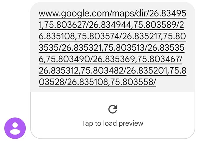
After that, we took the module outside and went for a walk and as you can see we received the GPS coordinates in the form of a text message.

When we clicked on the message, we saw something similar to what you can see in the image below.
![]()
This is the end of this vehicle tracking system using Arduino and A9G GPS module, and the complete working can also be found in the video given at the bottom of this page. Hope you understood the tutorial and enjoyed building something useful with it. If you have any doubts, you can leave them in the comment section below.
We have also build many other types of vehicle tracking systems previously, you can check them out if interested
Complete Project Code
#include <TinyGPSPlus.h>
#include <SoftwareSerial.h>
static const int RXPin = 6, TXPin = 5;
String s = "www.google.com/maps/dir/";
unsigned long interval = 10000;
static const uint32_t GPSBaud = 9600;
unsigned long previousMillis = 0;
int data_counter;
const size_t BUFSIZE = 300;
char f_buffer[BUFSIZE];
float *f_buf = (float*)f_buffer;
TinyGPSPlus gps;// The TinyGPSPlus object
SoftwareSerial ss(RXPin, TXPin);// The serial connection to the GPS device
void setup()
{
  Serial.begin(9600);
  ss.begin(GPSBaud);
  Serial.println("Starting...");
  ss.println("\r");
  ss.println("AT\r");
  delay(10);
  ss.println("\r");
  ss.println("AT+GPS=1\r");
  delay(100);
  ss.println("AT+CREG=2\r");
  delay(6000);
  //ss.print("AT+CREG?\r");
  ss.println("AT+CGATT=1\r");
  delay(6000);
  ss.println("AT+CGDCONT=1,\"IP\",\"WWW\"\r");
  delay(6000);
  // ss.println("AT+LOCATION=1\r");
  ss.println("AT+CGACT=1,1\r");
  delay(6000);
  //Initialize ends
  //Initialize GPS
  ss.println("\r");
  ss.println("AT+GPS=1\r");
  delay(1000);
  //ss.println("AT+GPSMD=1\r");   // Change to only GPS mode from GPS+BDS, set to 2 to revert to default.
  ss.println("AT+GPSRD=10\r");
  delay(100);
  // set SMS mode to text mode
  ss.println("AT+CMGF=1\r");
  delay(1000);
  //ss.println("AT+LOCATION=2\r");
  Serial.println("Setup Executed");
}
void loop() {
//    if (Serial.available()) {      // If anything comes in Serial (USB),
//      ss.write(Serial.read());   // read it and send it out ss (pins 0 & 1)
//    }
//
//    if (ss.available()) {     // If anything comes in ss (pins 0 & 1)
//      Serial.write(ss.read());   // read it and send it out Serial (USB)
//    }
  smartDelay(2000);
  if (millis() > 5000 && gps.charsProcessed() < 10)
    Serial.println(F("No GPS data received: check wiring"));
  unsigned long currentMillis = millis();
  if ((unsigned long)(currentMillis - previousMillis) >= interval) {
    send_gps_data();
    previousMillis = currentMillis;
  }
}
static void smartDelay(unsigned long ms)
{
  unsigned long start = millis();
  do
  {
    while (ss.available())
      gps.encode(ss.read());
  } while (millis() - start < ms);
}
void send_gps_data()
{
  if (gps.location.lat() == 0 || gps.location.lng() == 0)
  {
    Serial.println("Return Executed");
    return;
  }
  data_counter++;
  Serial.print("Latitude (deg): ");
  f_buf[data_counter] = gps.location.lat();
  Serial.println(f_buf[data_counter]);
  Serial.print("Longitude (deg): ");
  f_buf[data_counter + 1] = gps.location.lng();
  Serial.println(f_buf[data_counter + 1]);
  Serial.println(data_counter);
  Serial.println();
  s += String(gps.location.lat(), 6);
  s += ",";
  s += String(gps.location.lng(), 6);
  s += "/";
  Serial.println(s);
  if (data_counter >= 10)
  {
    data_counter = 0;
    Serial.println("Sending Message");
    ss.println("AT+CMGF=1\r");
    delay(1000);
    ss.println("AT+CNMI=2,2,0,0,0\r");
    delay(1000);
    ss.print("AT+CMGS=\"+91xxxxxxxxxx\"\r");//Replace this with your mobile number
    delay(1000);
    ss.print(s);
    ss.write(0x1A);
    delay(1000);
    s = "www.google.com/maps/dir/";
  }
}


