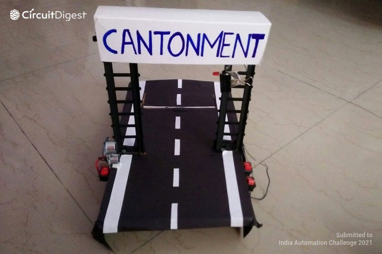
A lot of intrusion activities/security threats in the army area are seen nowadays. This gave me an idea to build something that helps the army and worked on it. I implemented this project by thinking about the basic idea of my project and using the materials required to detect movements and using Arduino to send commands to Servo motor and Ultrasonic Sensor. Not only in the army but it can be implemented anywhere where security arrangements are required.
Component Required for Anti Trespass Road System

Project Used Hardware
- Arduino UNO,
- Servo Motor,
- Ultrasonic Sensor,
- Buzzer,
- LED Bulb,
- Arduino Cable,
- 9V Battery,
- 3V Battery,
- SPST (Single Pole Single Throw) Switch
Project Used Software
- Arduino IDE
Project Hardware Software Selection
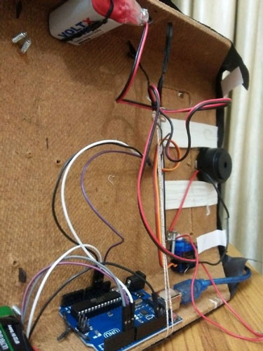
Arduino UNO was used to send commands to the other components. Servo Motor was used to lift up the road. Buzzer was used as a security alarm. Ultrasonic Sensor was used to detect suspicious movement. An LED Bulb was used to show the prohibited zone. Arduino Cable was used to give power to Arduino. A 9V Battery was used to give power to the buzzer. A 3V Battery was used to give power to the LED. SPST (Single Pole Single Throw) Switch was used to control the power supply. Software Selection: Arduino IDE was used to program Arduino UNO and transfer the program instructions to Arduino UNO.
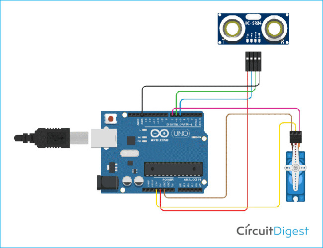
Anti Trespass Road System Circuit Diagram
The Vcc pin of the ultrasonic sensor is connected to the 5V power pin of the Arduino UNO. The trigger pin of the ultrasonic sensor is connected to digital pin number 5 of the Arduino UNO. The echo pin of the ultrasonic sensor is connected to digital pin number 6 of the Arduino UNO. The ground pin of the ultrasonic sensor is connected to the Digital Ground pin of the Arduino UNO. The negative terminal of the servo motor is connected to the Ground pin of the Arduino UNO. The positive terminal of the servo motor is connected to the 3.3V power pin of the Arduino UNO. The signal pin is connected to the Digital pin number 7 of the Arduino UNO.
Also check our previous projects on road safety protocols:
Complete Project Code
#include <Servo.h>   //servo library
Servo servo;
int trigPin = 5;
int echoPin = 6;
int servoPin = 7;
int led= 10;
long duration, dist, average;
long aver[3];   //array for average
void setup() {
    Serial.begin(9600);
    servo.attach(servoPin);
    pinMode(trigPin, OUTPUT);
    pinMode(echoPin, INPUT);
    servo.write(0);         //close cap on power on
    delay(100);
    servo.detach();
}
void measure() {
 digitalWrite(10,HIGH);
digitalWrite(trigPin, LOW);
delayMicroseconds(5);
digitalWrite(trigPin, HIGH);
delayMicroseconds(15);
digitalWrite(trigPin, LOW);
pinMode(echoPin, INPUT);
duration = pulseIn(echoPin, HIGH);
dist = (duration/2) / 29.1;    //obtain distance
}
void loop() {
  for (int i=0;i<=2;i++) {   //average distance
    measure();
   aver[i]=dist;
    delay(10);              //delay between measurements
  }
 dist=(aver[0]+aver[1]+aver[2])/3;
if ( dist<15 ) {
//Change distance as per your need
 servo.attach(servoPin);
  delay(1);
 servo.write(0);
 delay(3000);
 servo.write(1500);
 delay(1000);
 servo.detach();
}
Serial.print(dist);
}


