Winter is coming and that simply means cold weather with early nights. The perfect way to combat the winter gloom and lighten the mood is to light some candles but burning wax candles inside a closed room will fill up the room with carbon dioxide which can cause health issues. That is why in this article we have decided to build a moving flame electronics candle with Arduino and Attiny85 microcontroller the reason for adding a microcontroller to our project is to add some extra features, if you light up a match stick on top of the candle, the candle will light up and if you blow on top of the candle it will turn off the candle, by 3D printing an enclosure and the candle flame we can make the candlestick look even better, so without further ado let's get right into it
Designing the Digital Candle Housing and Flame using Fusion360
Once we decided on the design, we used fusion 360 to design the electronic candle as you can see it is shown in the below image.

Once this was complete, we designed the candle frame and printed it with the help of a 3D printing facility that we have in our lab. The candle flame looks like the below image shown below.

You can download STL files for both the candle and the flame by clicking on the STL File Link. To start with 3D printing you can follow our detailed article on Getting started with 3D printing.
How Does a Moving Flame Artificial Candle Light Work?
Before we go any further in the article, let's see how our digital candle will work. The block diagram of the 3D printed moving flame Electric candle is shown below,

The construction of the moving flame candle holder is very simple in the in the circuit we will have a battery that will power the microcontroller and the electromagnet the electromagnet is made from a 1” bolt raped with copper wire, when the microcontroller sends the trigger pulse to the MOSFET the coil energizes, and the bolt will turn into a magnet.

The flame of the candle is made of 3D printing, and I have attached a hexagonal nut to the stick portion of the candle flame now when the electromagnet is turned on it attracts the nut and that will move the flame.
As we are using a microcontroller as the brains for the project, we have decided to add some extra features to the candle by putting a match on top of the candle with light it up and by blowing it will turn it off. This can be done because of the LDR sensor, and the microphone attached to it. When a little light goes inside the candle the LDR recognizes the light and lights up the candle, when you blow the candle, the microphone recognizes the sound and turns off the lights and electromagnet and that is how the candle will work.
Components Required to build a 3D Printed Candle
The components required to build the 3D Printed Arduino Flicker candle are easier to get and can be found in your local hobby store, the components list is given below.
- ATtiny85 - 1
- Perfboard with Single Dot - 1
- IRF540L(Logic Level MOSFET) - 1
- mm Copper Wire
- Screw with Bolt
- Amber or Yellow LEDs - 2
- Slider Switch - 1
- Microphone Module - 1
- LDR - 1
- 10K Resistor - 1
- 1K resistor - 1
- 100R Resistor - 1
- 1R Resistor - 1
- 1N4007 Diode - 1
- 680uF,16V Capacitor - 1
Circuitdiagram for a Digital Electronic Candle
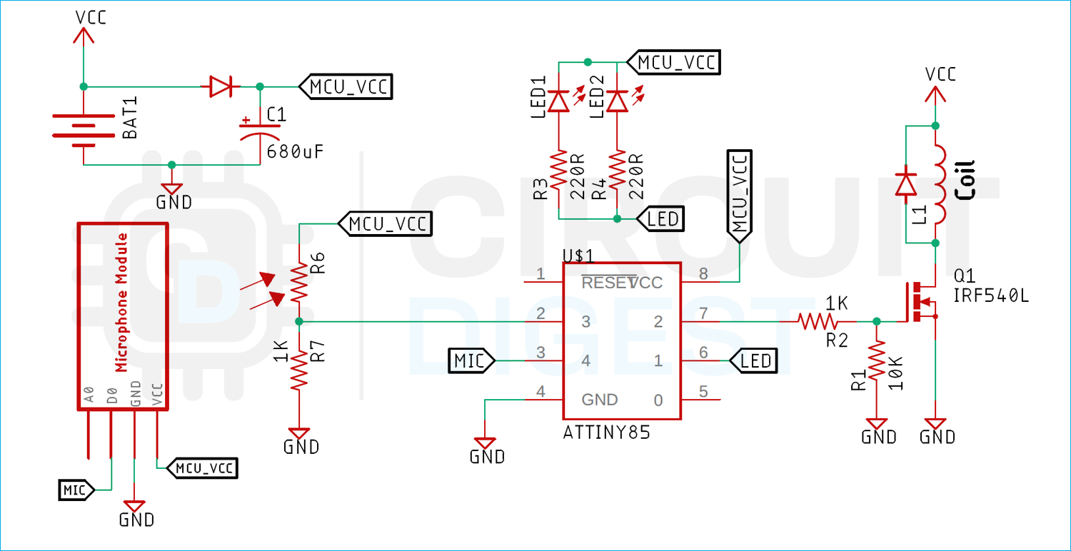
The schematic diagram of the moving flame electronics candle is very simple and easy to understand. The brain of the project is an ATtiny85 Microcontroller and in the section below we will explain how the circuit works.
The working of the circuit is very simple. In the circuit we have an Electromagnet (100 turns of 22 SWG wire) driven by a MOSFET, the MOSFET is driven by the ATtiny85 microcontroller whenever we enable the MOSFET it will energize the coil so the metal bolt we have used to wind the coil will turn into a electromagnet and the flame made out of 3D print will move as you can see in the construction section. We have made a voltage divider with the LDR and 1K resistor to sense the light and we have used a microphone model to sense the sound. Finally in the schematic we have 2-Yellow LEDs driven by the Microcontroller.
In the circuit the BAT1 is a single cell 3.7V lithium battery. The battery is powering the total circuit. As you can see, we have used a diode and a capacitor, it's mandatory because when the MOSFET turns on it creates a short circuit along the coil, the voltage drops to 0 for a fraction of a second and the microcontroller restarts. That is why the diode and capacitor become necessary. The diode provides an extra layer of protection keeping the microcontroller safe from EMF. Other than that, we have an LED and a Microphone module, if we light up a flame on top of the candle the LDR will sense the light and turn on the candle, and if we blow the candle the microphone module will recognize the sound and turn off the candle.
Arduino Code for Moving Flame Electronic Candle
The code for the Arduino based moving flame electronics candle is very simple and easy to understand. The whole code is explained below.
We start our code by including all the required variables: the first two sensor value variables are used to accrue the ADC value, and the trig variable is used to turn on and off the candle.
int sensorValue = 0;
int sensorValue2 = 0;
bool trig = 1;
In the setup function, there is also nothing much. We just make two digital pins as output; one is to drive the LED and another is to drive the electromagnet.
void setup() {
  // initialize digital pin LED_BUILTIN as an output.
  pinMode(2, OUTPUT);
  pinMode(1, OUTPUT);
}
Next, we have the loop function in the loop function. In the loop function we check the trig boolean status. If the flag is zero, we turn off the LEDs and the electromagnet and if the flag is 1 we light up the candle.
void loop() {
  if (trig == 0) {
    digitalWrite(2, HIGH);   // turn the LED on (HIGH is the voltage level)
    delay(100);
    digitalWrite(2, LOW);
    digitalWrite(2, LOW);
    delay(800);
}
In this section of the code, we read the ADC and value and store the value in the variable that we have defined.
  sensorValue = analogRead(A2);
  sensorValue2 = analogRead(A3);
If sensorValue2 is greater than the defined value, then we turn on the electromagnet and light the LED. If the sensorValue
  if (sensorValue2 > 9) {
    digitalWrite(1, LOW);
    trig =0;
  }
  if (sensorValue < 400) {
    digitalWrite(1, HIGH);
    trig =1;
  }
}
Testing our 3D Printed Candle Flame
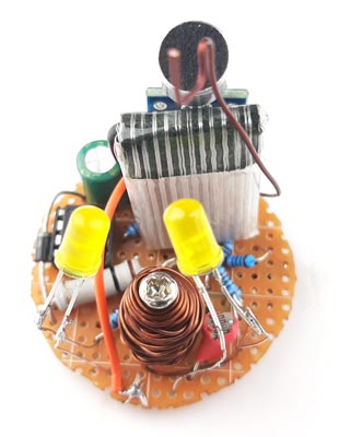
We started building the circuit according to the schematic and once it was finished it looked like something like the image shown below.

After the circuit was finished it looked like the image shown below and worked absolutely as expected.
The circuit worked fine, and the candle looks great but there are few problems in the circuit and that need to be fixed in the future version.
- The first problem is with the charging, this project does not have a charging port so the battery needs to be charged manually.
- There is no holder for the circuit board on the bottom of the candle; the design needs to change so that it could be locked or screwed to the bottom of the candle.
This is the end of this project and if you have any questions regarding this article, you can comment down below or you can ask in our forum.
Complete Project Code
int sensorValue = 0;
int sensorValue2 = 0;
int interval = 500;
bool trig = 1;
unsigned long previousMillis = 0;
void setup() {
  // initialize digital pin LED_BUILTIN as an output.
  pinMode(2, OUTPUT);
  pinMode(1, OUTPUT);
}
void loop() {
  if (trig == 0) {
    digitalWrite(2, HIGH);   // turn the LED on (HIGH is the voltage level)
    delay(100);
    digitalWrite(2, LOW);
    digitalWrite(2, LOW);
    delay(800);
  }
  sensorValue = analogRead(A2);
  sensorValue2 = analogRead(A3);
  if (sensorValue2 > 9)
  {
    digitalWrite(1, LOW);
    trig =0;
  }
  if (sensorValue < 400)
  {
    digitalWrite(1, HIGH);
    trig =1;
  }
}


