Motion detection is an essential part of security systems and PIR sensor is one of the most commonly used sensor for trigging the alarms when motion is detected. This sensor can detect human/animal movements easily by sensing the IR rays emitted by them. We previously used PIR sensor to build various kind of alarms and security systems:
Today we will build the same kind of Motion detection alarm by interfacing a PIR sensor with TI-MSP430.
Materials Required
- PIR Sensor Module
- TI-MSP430 Launchpad
- LED
- Buzzer
- Breadboard
- Jumper wires
PIR Sensor Module
The PIR sensor stands for Passive Infrared sensor which can detect many levels of radiations. As it is well known that every object emits some radiation and hotter materials emit more radiations than other materials. That’s why this sensor can detect human/animal presence because they are hotter than other materials in surrounding. The module consists a pyroelectric sensor, which detects the presence of human/animal body. And there is one Fresnel Lens attached to the sensor, which increases the range of the sensor. The pin-out for PIR sensor module is given below:


This module is adjustable i.e. the sensitivity and time trigger can be adjusted by rotating the knobs of two potentiometers on the board.
There are two modes of working: Retriggering (H) mode and non-Retriggering (I) mode.
In retriggering or H mode, the output stays high as long as the motion is occurring. And in non-retriggering or I mode, the output stays high then turns low after the trigger time and this process continues as long as motion is continued. Most applications use H mode and we’re also going to use this mode only. The PIR sensor works on 5V to 12V power supply. But it can also be powered by 3.3V pins of the MSP430.
To learn more about PIR sensor, follow the link and also learn how PIR sensor can be used with with Arduino, Raspberry Pi and other microcontrollers for various applications:
- Arduino Motion Detector using PIR Sensor
- Raspberry Pi Motion Sensor Alarm using PIR Sensor
- Interfacing PIR Sensor with PIC Microcontroller
- IOT based Security System with Voice Message Using ESP8266
Interfacing PIR Sensor Module with TI-MSP430
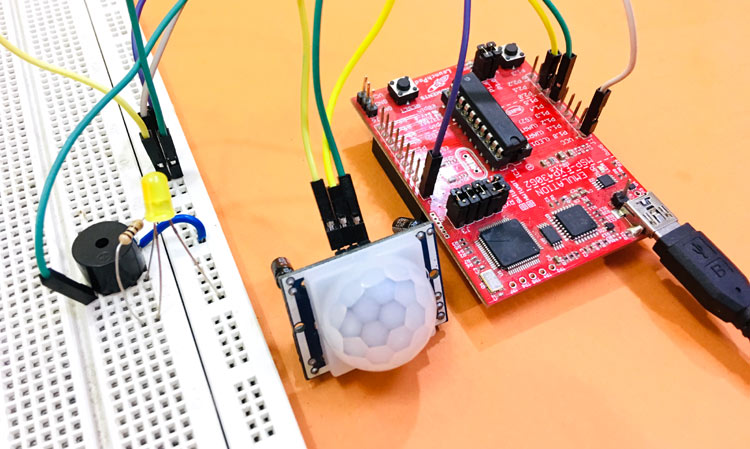
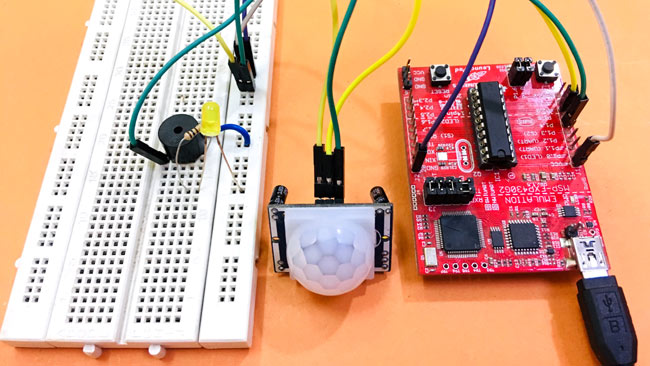
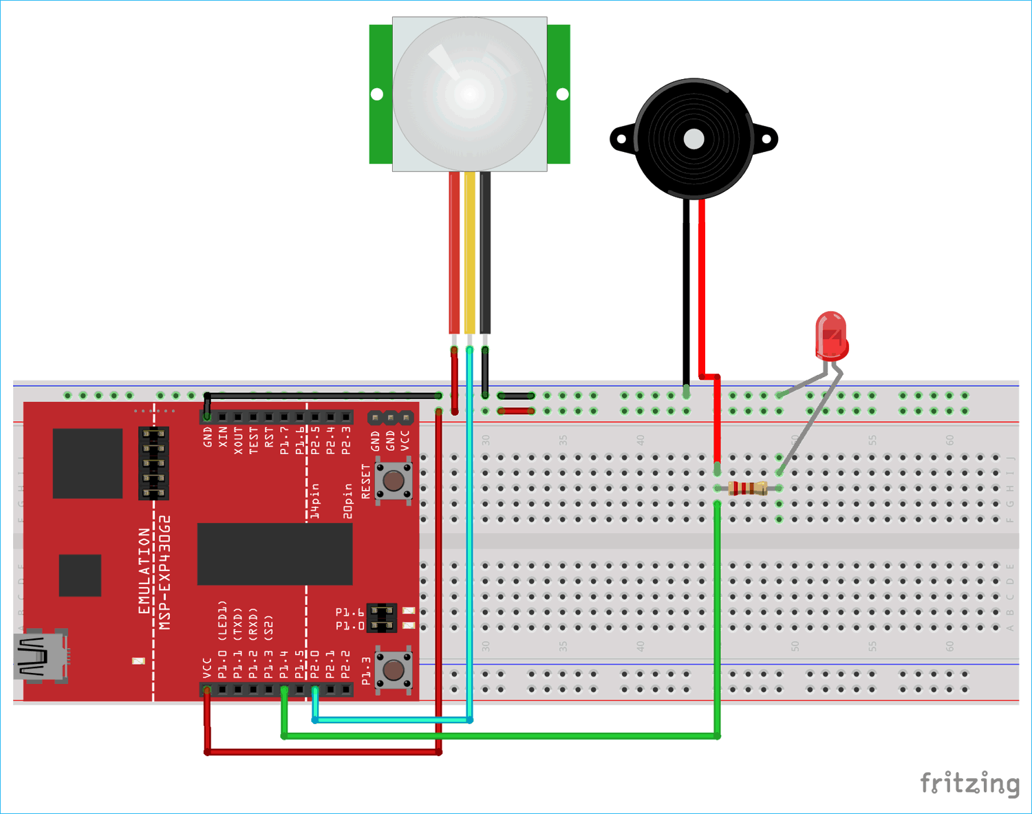
Connecting PIR Sensor with MSP430 is very easy. The VCC and GND pins of module is connected to VCC and GND pins of MSP430. The output pin of module is connected to 8th pin (P2.0) of MSP430. Although any pin can be used but you have to state the mode of the pin as input. The 6th pin (P1.4) is connected to LED and buzzer.

Programming PIR Sensor Module for TI-MSP430
The code is very simple and given at the end of this project with a Demonstration Video. Here we are going to blink the LED and beep the buzzer continuously when any motion gets detected by PIR sensor.
In setup function, we declare that the pin 8 will be used as input pin because it is fetching the output from PIR module and the pin 6 will be used as an output pin as it is connected to LED and buzzer.
void setup()
{
     pinMode(8, INPUT);
     pinMode(6, OUTPUT);
}
Next in the loop function, firstly we check for the output from PIR module whether it is high or not. Now if the output from PIR module is high then, it means that some movement is detected. So to indicate this, we turn the pin 6 low and high with a time delay of 100 milli seconds, so that continuous flashing and buzzing can be experienced.
void loop()
{
     If(digitalRead(8) == HIGH)
     {
          digitalWrite(6, HIGH);
          delay(100);
          digitalWrite(6, LOW);
          delay(100);
}
}

Finally upload the code to MSP430 using Energia IDE and power the board and wait for about a minute. The PIR sensor module takes some time to calibrate. After a minute, move your hand in front of sensor, and it works. After removing your hand the flashing and buzzing will stop. You can also try changing the sensitivity and time trigger using the two potentiometers present on the PIR sensor.
Complete Project Code
void setup()

{

  pinMode(8, INPUT);

  pinMode(6, OUTPUT);

}

void loop()

{

  If(digitalRead(8) == HIGH)

  {

    digitalWrite(6, HIGH);

    delay(100);

    digitalWrite(6, LOW);

    delay(100);

  }

}


