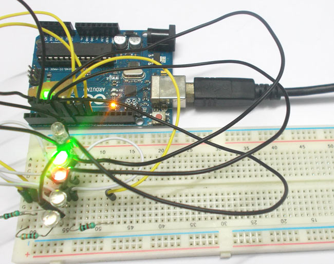
In this project we are going to interface 5 RGB (Red Green Blue) LEDs to Arduino Uno. These LEDs are connected in parallel for reducing PIN usage of Uno.
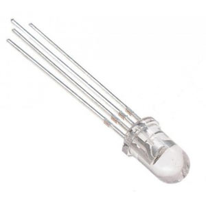
A typical RGB LED is shown in below figure:

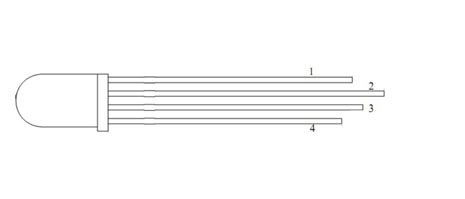
The RGB LED will have four pins as shown in figure.
PIN1: Color 1 negative terminal or color 1 positive terminal
PIN2: Common positive for all three colors or common negative for all three colors
PIN3: Color 2 negative terminal or color 2 positive terminal
PIN4: Color 3 negative terminal or color 3 positive terminal

So there are two types of RGB LEDs, one is common cathode type (common negative) and other is common anode type (common positive) type. In CC (Common Cathode or Common Negative), there will be three positive terminals each terminal representing a color and one negative terminal representing all three colors. The internal circuit of a CC RGB LED can be represented as below.

If we want RED to be on in above, we need to power the RED LED pin and ground the common negative. The same goes for all the LEDs. In CA (Common Anode or Common Positive), there will be three negative terminals each terminal representing a color and one positive terminal representing all three colors. The internal circuit of a CA RGB LED can be represented as shown in figure..
If we want RED to be on in above, we need to ground the RED LED pin and power the common positive. The same goes for all the LEDs.
In our circuit we are going to use CA (Common Anode or Common Positive) type. For connecting 5 RGB LEDs to Arduino we need 5x4= 20 PINS usually, by we are going to reduce this PIN usage to 8 by connecting RGB LEDs in parallel and by using a technique called multiplexing.
Components
Hardware: UNO, power supply (5v), 1KΩ resistor (3 pieces), RGB (Red Green Blue) LED (5 pieces)
Software: Atmel studio 6.2 or Aurdino nightly.
Circuit and Working Explanation
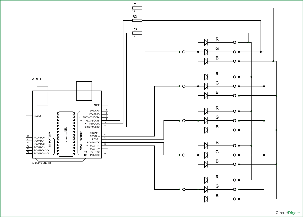
The circuit connection for RGB LED Arduino interfacing is shown in below figure.
Now for the tricky part, say we want to turn the RED led in SET1 and GREEN LED in SET2. We power the PIN8 and PIN9 of UNO, and ground PIN7, PIN6.
With that flow we will have RED in first SET and GREEN in second SET ON, but we will have GREEN in SET1 and RED in SET2 ON with it. By simple analogy we can seen all four LEDs close the circuit with above configuration and so they all glow.
So to eliminate this problem we will turn only one SET on at a time. Say at t=0m SEC, SET1 is tuned ON. At t = 1m SEC, SET1 is tuned OFF and SET2 is turned ON. Again at t=6m SEC, SET5 is turned OFF and SET1 is turned ON. This goes on.
Here the trick is, the human eye cannot capture a frequency more than 30 HZ. That is if a LED goes ON and OFF continuously at a rate of 30HZ or more. The eye sees the LED as continuously ON. However this is not the case. The LED will be constantly turning ON and OFF. This technique is called multiplexing.
Simply speaking we will power each common cathode of 5 SETs 1milli second, so in 5milli second we will have completed the cycle, after that the cycle starts from SET1 again, this goes on forever. Since the LED SETs are going ON and OFF too fast. The human predicts all the SETs are ON all the time.
So when we power SET1 at t=0 milli second, we ground the RED pin. At t=1 milli second, we power the SET2 and ground the GREEN pin (at this time RED and BLUE are pulled up HIGH). The loop goes fast and the eye sees RED glow in FIRST SET and GREEN glow in SECOND SET.
This is how we program a RGB LED, we will glow all the colors slowly in program to see how multiplexing works.
Complete Project Code
void setup()
{
                for (int i=0;i<11;i++)//all first 11 pins are set as OUTPUT
                {
                                pinMode(i, OUTPUT);
                }
                for (int i=3;i<8;i++)
                {
                                digitalWrite(i, LOW);//pins3-8 are set low
                }
}
// the loop routine runs over and over again forever:
void loop()
{
                for (int i=3;i<8;i++)
                {
                                digitalWrite(i,HIGH);//power each set one time
                                for (int j=8;j<11;j++)
                                {
                                                digitalWrite(j,LOW);
                                                delay(100);
                                                digitalWrite(j,HIGH);//blink three colors of each set
                                }
                                digitalWrite(i,LOW);//pull down power set after blinking the colors.
                }
}


