Power consumption is a critical issue for a device running continuously for a long time without being turned off. So to overcome this problem almost every controller comes with a sleep mode, which help developers to design electronic gadgets for optimal power consumption. Sleep mode puts the device in power saving mode by turning off the unused module.
Earlier we have explained Deep-sleep mode in ESP8266 for Power Saving. Today we will learn about Arduino Sleep Modes and demonstrate power consumption by using Ammeter. An Arduino Sleep mode is also referred as Arduino Power Save mode or Arduino Standby Mode.
Arduino Sleep Modes
Sleep Modes allow the user to stop or turn off the unused modules in the Microcontroller which significantly reduce the power consumption. Arduino UNO, Arduino Nano and Pro-mini comes with ATmega328P and it has a Brown-out Detector (BOD) which monitors the supply voltage at the time of sleep mode.
There are six sleep modes in ATmega328P:
For entering into any of the sleep mode we need to enable the sleep bit in the Sleep Mode Control Register (SMCR.SE). Then the sleep mode select bits select the sleep mode among Idle, ADC noise reduction, Power-Down, Power-Save, Standby and External Standby.
An internal or external Arduino interrupts or a Reset can wake up the Arduino from the sleep mode.
Idle Mode
For entering into the Idle sleep mode, write the SM[2,0] bits of the controller ‘000’. This mode stops the CPU but allow the SPI, 2-wire serial interface, USART, Watchdog, counters, analog comparator to operate. Idle mode basically stops the CLKCPU and CLKFLASH. Arduino can be waked up any time by using external or internal interrupt.
Arduino Code for Idle Sleep Mode:
LowPower.idle(SLEEP_8S, ADC_OFF, TIMER2_OFF, TIMER1_OFF, TIMER0_OFF, SPI_OFF, USART0_OFF, TWI_OFF);
There is a library for setting various low power modes in arduino. So first download and install the library from the given link and use the above code to put the Arduino in Idle Sleep Mode. By using the above code, the Arduino will go into a sleep of eight seconds and wake up automatically. As you can see in the code that the idle mode turns off all the timers, SPI, USART, and TWI (2-wire interface).
ADC Noise Reduction Mode
To use this sleep mode write the SM[2,0] bit to ‘001’. The mode stops the CPU but allow the ADC, external interrupt, USART, 2-wire serial interface, Watchdog, and counters to operate. ADC Noise Reduction mode basically stops the CLKCPU, CLKI/O and CLKFLASH. We can wake up the controller from the ADC Noise Reduction mode by the following methods:
- External Reset
- Watchdog System Reset
- Watchdog Interrupt
- Brown-out Reset
- 2-wire Serial Interface address match
- External level interrupt on INT
- Pin change interrupt
- Timer/Counter interrupt
- SPM/EEPROM ready interrupt
Power-Down Mode
Power-Down mode stops all the generated clocks and allows only the operation of asynchronous modules. It can be enabled by writing the SM[2,0] bits to ‘010’. In this mode, the external oscillator turns OFF, but the 2-wire serial interface, watchdog and external interrupt continues to operate. It can be disabled by only one of the method below:
- External Reset
- Watchdog System Reset
- Watchdog Interrupt
- Brown-out Reset
- 2-wire Serial Interface address match
- External level interrupt on INT
- Pin change interrupt
Arduino Code for Power-Down Periodic Mode:
LowPower.powerDown(SLEEP_8S, ADC_OFF, BOD_OFF);
The code is used to turn on the power-down mode. By using the above code, the Arduino will go into a sleep of eight seconds and wake up automatically.
We can also use the power-down mode with an interrupt, where the Arduino will go into sleep but only wakes up when an external or internal interrupt is provided.
Arduino Code for Power-Down Interrupt Mode:
void loop()
{
    // Allow wake up pin to trigger interrupt on low.
    attachInterrupt(0, wakeUp, LOW);

    LowPower.powerDown(SLEEP_FOREVER, ADC_OFF, BOD_OFF);
    // Disable external pin interrupt on wake up pin.

    detachInterrupt(0);

    // Do something here
}
Power-Save Mode
To enter into the power-save mode we need to write the SM[2,0] pin to ‘011’. This sleep mode is similar to the power-down mode, only with one exception i.e. if the timer/counter is enabled, it will remain in running state even at the time of sleep. The device can be waked up by using the timer overflow.
If you are not using the time/counter, it is recommended to use Power-down mode instead of power-save mode.
Standby Mode
The standby mode is identical to the Power-Down mode, the only difference in between them is the external oscillator kept running in this mode. For enabling this mode write the SM[2,0] pin to ‘110’.
Extended Standby Mode
This mode is similar to the power-save mode only with one exception that the oscillator is keep running. The device will enter into the Extended Standby mode when we write the SM[2,0] pin to ‘111’. The device will take six clock cycles to wake up from the extended standby mode.
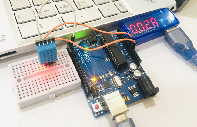
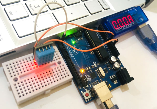
Below are the requirements for this project, after connecting the circuit as per the circuit diagram. Upload the sleep mode code into Arduino using Arduino IDE. Arduino will enter into the idle sleep mode. Then check the current consumption into the USB ammeter. Else, you can also use a clamp meter for the same.
Components Required
- Arduino UNO
- DHT11 Temperature and Humidity Sensor
- USB Ammeter
- Breadboard
- Connecting Wires
To learn more about using DHT11 with Arduino, follow the link. Here we are using USB Ammeter to measure the voltage consumed by Arduino in sleep mode.
USB Ammeter
USB ammeter is a plug and play device used to measures the voltage and current from any USB port. The dongle plugs in between the USB power supply (computer USB port) and USB device (Arduino). This device have a 0.05ohm resistor in-line with the power pin through which it measures the value of current drawn. The device comes with four seven segment display, which instantly display the values of current and voltage consumed by the attached device. These values flips in an interval of every three seconds.
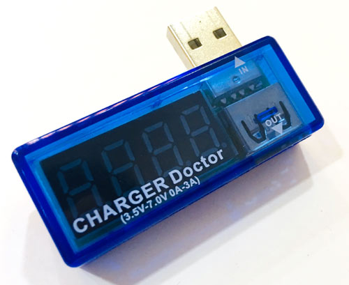
Specification:
- Operating voltage range: 3.5V to 7V
- Maximum current rating: 3A
- Compact size, easy to carry
- No external supply needed
Application:
- Testing USB devices
- Checking load levels
- Debugging battery chargers
- Factories, electronics products and personal use
Circuit Diagram
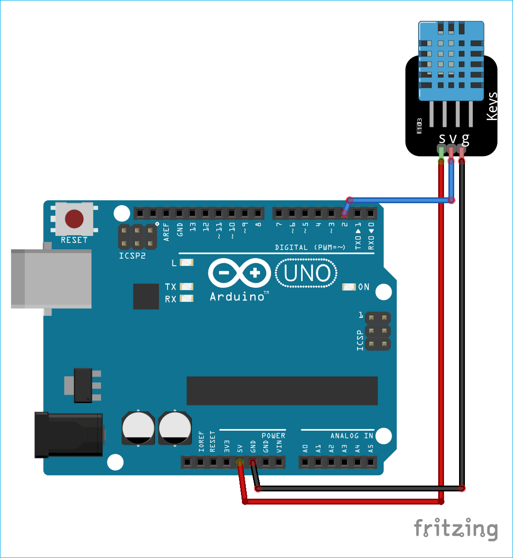
In the above setup to demonstrate Arduino Deep sleep modes, the Arduino is plugged into the USB ammeter. Then the USB ammeter is plugged into the USB port of the laptop. Data pin of the DHT11 sensor is attached to the D2 pin of the Arduino.
Code Explanation
The complete code for the project with a video is given at the end.
The code start by including the library for the DHT11 sensor and the LowPower library. For downloading the Low Power library follow the link. Then we have defined the Arduino pin number to which the data pin of the DHT11 is connected and created a DHT object.
#include <dht.h>
#include <LowPower.h>

#define dataPin 2
dht DHT;
In the void setup function, we have initiated the serial communication by using serial.begin(9600), here the 9600 is the baud rate. We are using Arduino’s built-in LED as an indicator for the sleep mode. So, we have set the pin as output, and digital write low.
void setup() {
  Serial.begin(9600);
  pinMode(LED_BUILTIN,OUTPUT);
  digitalWrite(LED_BUILTIN,LOW);
}
In the void loop function, we are making the built-in LED HIGH and the reading the temperature and humidity data from the sensor. Here, DHT.read11(); command is reading the data from the sensor. Once data is calculated, we can check the values by saving it into any variable. Here, we have taken two float type variables ‘t’ and ‘h’. Hence, the temperature and humidity data is printed serially on the serial monitor.
void loop() {
  Serial.println("Get Data From DHT11");
  delay(1000);
  digitalWrite(LED_BUILTIN,HIGH);
  int readData = DHT.read11(dataPin); // DHT11

  float t = DHT.temperature;
  float h = DHT.humidity;

  Serial.print("Temperature = ");
  Serial.print(t);
  Serial.print(" C | ");

  Serial.print("Humidity = ");
  Serial.print(h);
  Serial.println(" % ");

  delay(2000);
Before enabling the sleep mode we are printing "Arduino: - I am going for a Nap" and making the built in LED Low. After that Arduino sleep mode is enabled by using the command mentioned below in the code.
Below code enables the idle periodic sleep mode of the Arduino and gives a sleep of eight seconds. It turns the ADC, Timers, SPI, USART, 2-wire interface into the OFF condition.
Then it automatically wakes up Arduino from the sleep after 8 seconds and print “Arduino:- Hey I just Woke up”.
  Serial.println("Arduino:- I am going for a Nap");
  delay(1000);
  digitalWrite(LED_BUILTIN,LOW);
  LowPower.idle(SLEEP_8S, ADC_OFF, TIMER2_OFF, TIMER1_OFF, TIMER0_OFF,
                 SPI_OFF, USART0_OFF, TWI_OFF);
  Serial.println("Arduino:- Hey I just Woke up");
  Serial.println("");
  delay(2000);
}
So by using this code Arduino will be only wake up for 24 seconds in a minute and will remain in sleep mode for rest of the 36 seconds, which significantly reduce the power consumed by the Arduino weather station.

Therefore, if we use the Arduino with the sleep mode, we can approximately double the device runtime.
Complete Project Code
Arduino Weather Station with Sleep Mode
#include <dht.h>
#include <LowPower.h>
#define dataPin 2
dht DHT;
void setup() {
  Serial.begin(9600);
  pinMode(LED_BUILTIN,OUTPUT);
  digitalWrite(LED_BUILTIN,LOW);
}
void loop() {
  Serial.println("Get Data From DHT11");
  delay(1000);
  digitalWrite(LED_BUILTIN,HIGH);
  int readData = DHT.read11(dataPin); // DHT11
  float t = DHT.temperature;
  float h = DHT.humidity;
  Serial.print("Temperature = ");
  Serial.print(t);
  Serial.print(" C | ");
  Serial.print("Humidity = ");
  Serial.print(h);
  Serial.println(" % ");
  delay(2000);
  Serial.println("Arduino:- I am going for a Nap");
  delay(200);
  digitalWrite(LED_BUILTIN,LOW);
  LowPower.idle(SLEEP_8S, ADC_OFF, TIMER2_OFF, TIMER1_OFF, TIMER0_OFF,
                 SPI_OFF, USART0_OFF, TWI_OFF);
  Serial.println("Arduino:- Hey I just Woke up");
  Serial.println("");
  delay(2000);
}
Arduino Weather Station without Sleep Mode
#include <dht.h>
#define dataPin 2
dht DHT;
void setup() {
  Serial.begin(9600);
  pinMode(LED_BUILTIN,OUTPUT);
  digitalWrite(LED_BUILTIN,LOW);
}
void loop() {
  digitalWrite(LED_BUILTIN,HIGH);
  int readData = DHT.read11(dataPin); // DHT11
  float t = DHT.temperature;
  float h = DHT.humidity;
  Serial.print("Temperature = ");
  Serial.print(t);
  Serial.print(" C | ");
  Serial.print("Humidity = ");
  Serial.print(h);
  Serial.println(" % ");
  delay(2000);
}


