The MSP-EXP430G2 is a Development Tool a.k.a LaunchPad provided by the Texas Instruments to learn and practice on how to use their Microcontrollers. This board falls under the MSP430 Value Line category where we can program all the MSP430 series Microcontrollers. Learning how to use TI Microcontrollers would definitely be a mighty tool up in our sleeve because TI is really huge and has a wide verity of MCU’s to choose from for a very less competitive price.
We already covered detailed article on using Energia IDE with MSP430. In this tutorial we will learn about Code Composer Studio and how it is used to program MSP430. This tutorial is written for very beginners and no hardware is required except the MSP430 board and a computer. At the end of this tutorial we will be able to Blink the onboard LED of MSP430.
MSP-EXP430G2 Development Board:
The gorgeous red colour board is the MSP-EXP430G2 Development Board. This board can program TI Microcontrollers that fall under the MSP430 series. The main purpose of this board it to upload code from the computer to the MCU and read serial data from the MCU for debugging purpose. It also provides the pin-out for each pin of the MCU and also two LEDs and a push button to make development easy. The board has evolved a lot since its launch and the one shown below is the MSP_EXP430G2 Rev1.5.
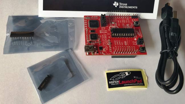
The MSP430G2553 has better specifications than the other series, it also has a UART module which would be very handy while debugging using Code Composer Studio. Hence in this series of tutorials, we will be using the MSP430G2553 to explore all the functionalities of this Development kit.
Powering and Testing the development board:
Before we start anything TI would have already uploaded a sample Program on your MSP430G2553 Microcontroller, so let us power the board and check if it is working. You can power board through the mini USB jack and once you do it, you should notice the LEDs (red and green) at the bottom left corner of your board glowing alternatively. You can then press the push button connected to P1.3 to check if the internal temperature sensor is working. Yes, the MSP2553 has an internal temperature sensor, after pressing the button just rub your fingers to warm it up and place it on the IC you can notice the Red LED turns on to indicate the rise in temperature. Cool!! Right?? Okay now, let us move on to the Software Environment.
Programming Software (IDE) for MSP430 LaunchPad:
Texas Instruments allows us to program their Microcontrollers through a variety of Environments. The Official one is the Code Composer Studio commonly known as the CCS. This software is available free of cost. Also, it requires some minimal level of experience with Microcontrollers. Don’t worry we will cover every step to get familiar with CCS.
There is one more IDE available to write our program i.e. Energia IDE. So, what is the difference between CCS and Energia IDE. We already covered Energia IDE in our previous Tutorial.
Energia IDE vs. Code Composer Studio:
Energia is an Open source and free Environment that enables us to program the TI Microcontrollers easily. The main aim of Energia is to make programming TI MCU’s as easy as programming in Arduino. So Energia is an Equivalent for Arduino that supports Texas Instruments Microcontrollers. People who have used Arduino will agree more on this once they download and launch the Energia IDE.
Code Composer Studio (CCS) is a more versatile professional IDE which has more functionalities and capabilities in terms of accessing the inside architecture of microcontroller. It has inbuilt debugging function which can check errors in your code and you can run your code line by line that helps in finding error without any headache. It will take sometime to get comfortable with CCS. Once you set with this awesome software, trust me you will get to know anything about a particular microcontroller. You have to take help of Datasheet of the microcontroller to write your program.
If you are done with Arduino iDE or Energia IDE, change your coding environment to CCS, it is most demanding software in Industries.
Downloading and Launching the Code Composer Studio:
This software is available at Texas Instrument’s website without any cost. So, you can download it from the given link Download link .We will use Code Composer Studio V7 but you can download latest version also, procedure remains same.
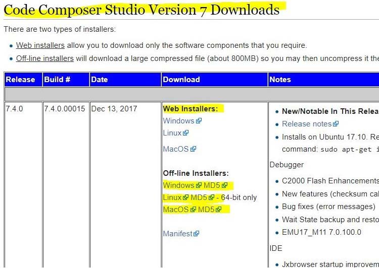
Either you can download whole software using web installer or download setup/off-line installer. This software is quite heavy around 1GB so, you need to wait until it finished downloading.
After downloading the software, open it and install.
When you click on setup, just like any other software you will be asked to agree terms and conditions and to select the installation folder. After that you have to choose boards for which you want to download files. In our case we are using MSP430 MCU, click on first option. You can download more than one board files.
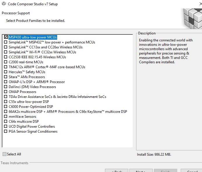
Next window is to select debug probe. By default one option is available so, click on it and finish. Now, your installation will start so just wait until it finished.
After installation, it asks about workspace folder so choose the folder where you want to save your files and click Ok.
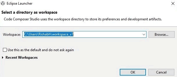
So, let’s take a look at the first window that we will see.
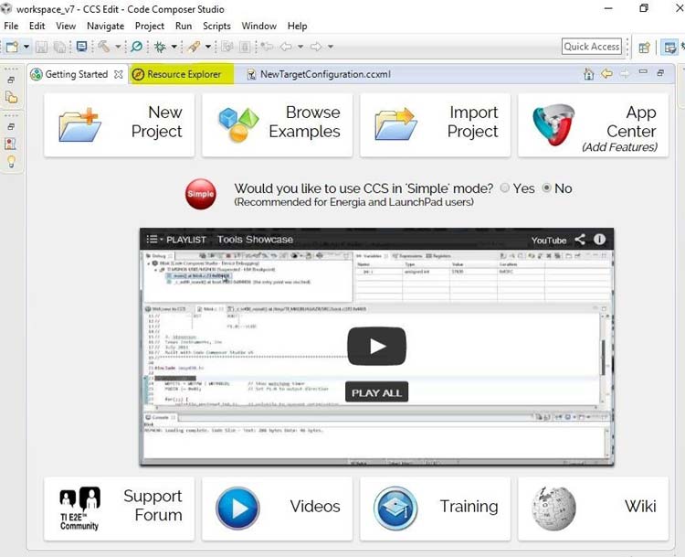
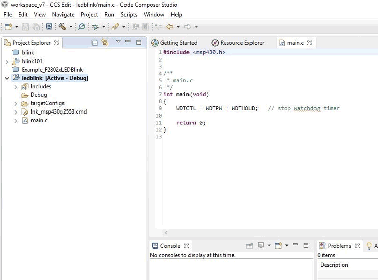
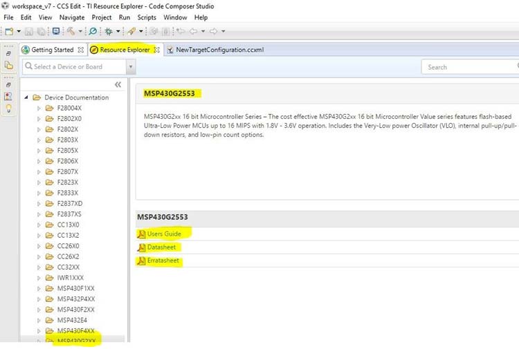
This is a simple interface where you can see Getting started menu in which you can start to make your project ,next to getting started there is a Resource Explorer. This is a awesome feature of this software in which you can find every detail of a TI product like datasheets, documentations, etc. There is no need to find datasheets on internet, just click on resource explorer and click on the device which you want to explore after that you can see every detail about the product.
Creating first Project in Code Composer Studio: Blink an LED:
Creating Project in CCS:
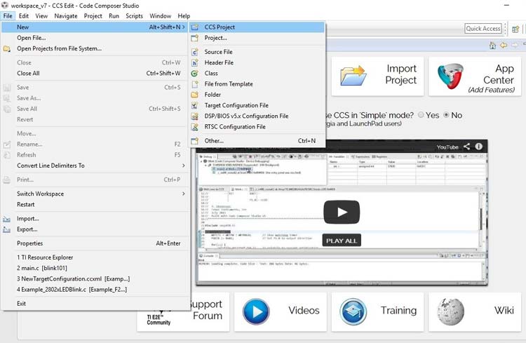
Step 1:- Click on File -> New -> CCS project. As shown below
Step 2:- Next, you have to choose MSP board that you are using. I am using MSP430G2553 so, I will choose this as shown.
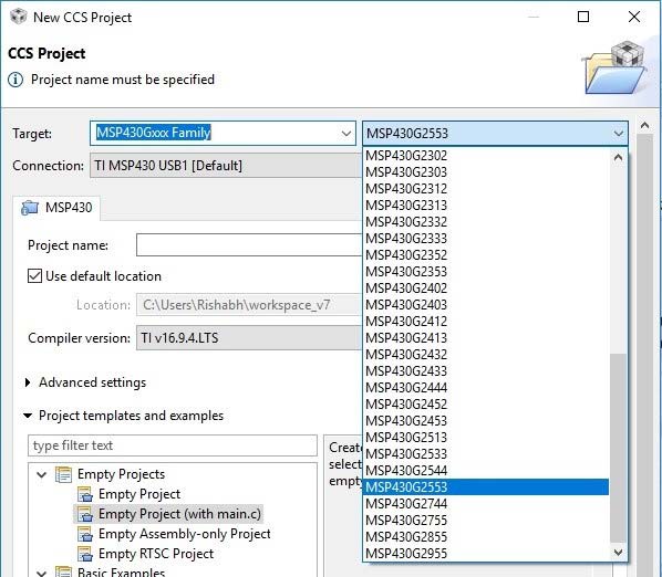
Give name to your project and click on finish.
As soon as you click on finish, a new window will open with some lines code already written into it.
Writing Code in CCS:
Let’s see the structure of the code that is already given. First line is our header file which depends on the variant that we choose while creating the project. As I told I am using MSP430G2553, so I’ll rename the header file to
#include<msp430g2553.h>
Next line is the main function. In the main function you will see initialization of Watchdog timer. MSP430 and other TI based microcontroller has special type of timer which is known as Watchdog timer . Work of this timer is to rset the microcontroller when it starts to hanging or stop giving response. In our code, we will not use Watchdog timer because it is above the beginner’s perspective. When we ON the Microcontroller, watchdog timer is ON by default so we have to OFF this timer by writing this line
WDTCTL = WDTPW | WDTHOLD;
Now, we have to write code to blink onboard LED which is connected to P1.0. There is another LED connected to P1.6. We will use only first LED. You are able to write code for toggling these two LED’s also after you understand the blink program.
First, we have to declare these PINS as we are using these as INPUT or OUTPUT.
There are many type of Registers i.e. memory blocks used to control PORTS. So, for defining PORT as INPUT or OUTPUT, PXDIR (X is port no.) (Data Direction Register) register is used. If PXDIR is 1 it acts as OUTPUT and 0 for INPUT. Our LED is at port no. 1 so we will write as P1DIR .
We need to configure PIN 0, as our LED is connected to this PIN and it is OUTPUT. Each port has 8 bits and we want Bit0 as HIGH to make it OUTPUT. So, we assign P1DIR as
P1DIR = 0b00000001;   it is in binary , we can also write it in Hexadecimal i.e.
P1DIR = 0x01;
Next, we have to set the particular pin of particular port as high or low. For this purpose we have to use P1OUT register, 1 for high while 0 for low. Initially, I make the LED ON by setting BIT0 as 1 other remains zero.
P1OUT=0b00000001;
P1OUT = 0x01; //in hexadecimal
As there is no inbuilt function of delay in MSP430 so, we have to use for loop to provide delay.
So, in next step, we have to declare a variable ‘i’ for delay purpose which can be written as
Unsigned int i;
First, we will make PIN0 HIGH and give some delay using FOR loop after that make the PIN LOW. In this way, we get blinking effect. We write program like this:
  P1OUT=0X01;   //make bit0 HIGH
        for(i=0;i<20000;i++){   //    delay till you make LED HIGH
    }
        P1OUT=0X00;   //make bit0 LOW

        for(i=0;i<20000;i++){   // delay till you make LED LOW
               }
You can write this code in another way also. You can use BITWISE operator to reduce lines of code. There are OR, AND and XOR bitwise operators available. You can use XOR operator (^) . XOR operation gives 1 when both bits are equal like 1 and 1, 0 and 0 .We write it like this
P1OUT ^= 0x01;
which means P1OUT = P1OUT xor 0b00000001;
So, initially we initialize P1OUT as 0b00000001, if we take xor operation with 0b00000001, output will be 0b00000000 means our LED will be OFF. After this we put for loop for delay purpose.
while(1)
    {
        P1OUT ^=0X01;   //toggle the bits

        for(i=0;i<20000;i++){   // delay till you make LED LOW HIGH
  }
    }
Upload the code into MSP430:
Complete program for CCS is given at the end of the page. So our code is ready to burn in MSP430. So, connect MSP with your laptop using USB cable.
Now, we have to compile/build our code, for this click on Project -> Build All. Check the report of compilation in the console box at the bottom of the window. It will show “Build Finished”.
It’s time to upload the program. Click on Run -> Debug. After clicking on debug, you will get a window related to power saving, just click on proceed. In debug option go to Run->Resume. If your options are blanked out, no need to worry, go to View->Debug and then again go to Run->Resume.
As soon as you debugged the code, your program is uploaded in the MSP. A shortcut way is to simply click the play/pause like button on the screen. The debug screen will look like, as given below
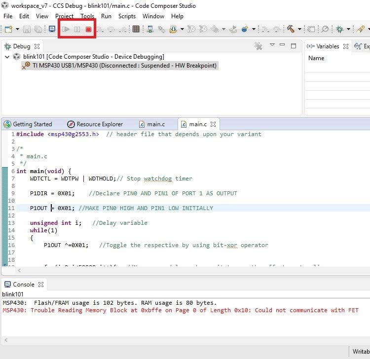
If LED is not blinking then Reset the board or connect the USB again.
SO this is how you can write a simple program in Code Composer Studio to blink a LED using MSP430.
Complete Project Code
#include <msp430g2553.h>  // header file that depends upon your board
/*
 * main.c
 */
int main(void) {
    WDTCTL = WDTPW | WDTHOLD;// Stop watchdog timer
    P1DIR = 0X01;    //Declare PIN0 OF PORT 1 AS OUTPUT
    P1OUT = 0X01; //MAKE PIN0 HIGH INITIALLY
    unsigned int i;   //Delay variable
    while(1)
    {
        P1OUT ^=0X01;   ////toggle the bits
        for(i=0;i<20000;i++){   // delay till you make LED LOW HIGH
  }
 }
    return 0;
}

