As the world is heading towards automation and artificial intelligence, different innovations are taking place every day to make things smarter and scalable. Nowadays in the era of the Internet of Things, everything is connected with the internet and a number of IoT enabled boards are coming in the market. We reviewed a few boards previously like PIC IoT WG Development, STM32F Nucleo-64 Development Boards, etc.
By observing the rapid growth of the IoT industry, some world-class IoT platform leaders like Particle cloud introduced there 3rd Generation IoT devices like Particle Argon, Xenon, Boron, etc.
These all are very versatile and powerful IoT development kits. These boards are all built around the Nordic nRF52840 SoC and include an ARM Cortex-M4F with 1MB of Flash and 256k of RAM. This chip supports Bluetooth 5 and NFC. Furthermore, the Argon adds WiFi with an ESP32 from Espressif. The Boron brings LTE to the table with a ublox SARA-U260 module, and the Xenon comes with WiFi and Cellular. These kits also support mesh networking which helps in expanding the IoT devices.
In this Getting started tutorial, we will unbox a new Particle Argon Kit and will see its features and demonstrate this kit with an example code of Blinky LED.
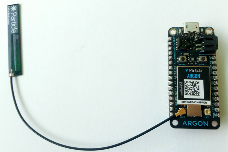
Particle Argon IoT Development Board- Hardware Explanation
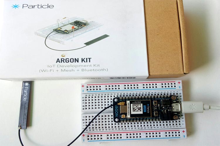
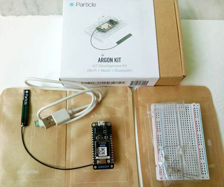
First, let’s see inside the box, you will find One Argon IoT board, a mini breadboard, a micro-USB cable, some LEDs, and resistors for getting started with the kit.
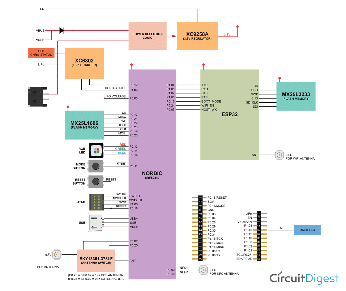
Now, understand the Argon board with the help of below Block Diagram.
As you can see in the block diagram, it has ESP32 and Nordic nRF core with ARM M4. It also has external flash memory and SWD connector for programming and debugging the code. On the power side, it has LiPo charging circuitry.
From the above Block diagram, we can list the features of the Argon board.
Features
- Espressif ESP32-D0WD 2.4 GHz Wi-Fi coprocessor
- On-board 4MB flash for ESP32
- 802.11 b/g/n support
- 802.11 n (2.4 GHz), up to 150 Mbps
- Nordic Semiconductor nRF52840 SoC
- ARM Cortex-M4F 32-bit processor @ 64MHz
- 1MB flash, 256KB RAM
- Bluetooth 5: 2 Mbps, 1 Mbps, 500 Kbps, 125 Kbps
- Supports DSP instructions, HW accelerated Floating Point Unit (FPU) calculations
- ARM TrustZone CryptoCell-310 Cryptographic and security module
- Up to +8 dBm TX power (down to -20 dBm in 4 dB steps)
- NFC-A tag
- On-board additional 4MB SPI flash
- 20 mixed signal GPIO (6 x Analog, 8 x PWM), UART, I2C, SPI
- Micro USB 2.0 full speed (12 Mbps)
- Integrated Li-Po charging and battery connector
- JTAG (SWD) Connector
- RGB status LED
- Reset and Mode buttons
- On-board PCB antenna
- U.FL connector for external antenna
So it is clear with the features of Argon particle board that it is capable of doing complex IoT tasks with the inbuilt ARM processor and RF chips.
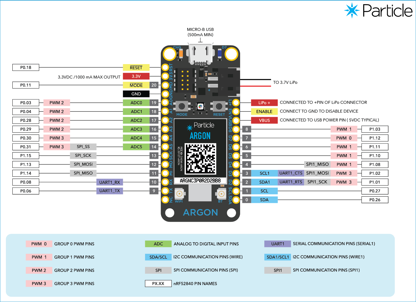
Now, let's see the Pin markings and Pin description of the Argon board.
Pin Markings
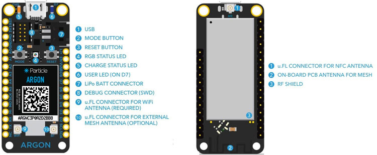
Pin Diagram
The maximum supply input voltage of the Argon board is +6.2v.
Pin Description
- Li+ => Pin is internally connected to the positive terminal of the LiPo battery connector.
- EN => Device enable pin is internally pulled up. To disable the device, connect this pin to GND.
3. VUSB => Pin is internally connected to the USB (+ve) supply.
4. 3V3 => Output of the onboard 3.3V regulator.
5. GND => System ground pin.
6. RST => Active-low system reset input. This pin is internally pulled-up.
7. MD => This pin is internally connected to the MODE button. The MODE function is active-low.
8. RX => Primarily used as UART RX, but can also be used as a digital GPIO.
9. TX => Primarily used as UART TX, but can also be used as a digital GPIO.
10. SDA => Primarily used as data pin for I2C, but can also be used as a digital GPIO.
11. SCL => Primarily used as clock pin for I2C, but can also be used as a digital GPIO.
12. MO, MI, SCK => These are the SPI interface pins, but can also be used as a digital GPIO.
13. D2-D8 => These are generic GPIO pins. D2-D8 are PWM-able.
14. A0-A5 => These are analog input pins that can also act as standard digital GPIO. A0-A5 are PWM-able.
Programming the Argon IoT Development Boards
There are many ways to program any Particle board. You can use Web IDE to write and upload code from anywhere in the world, this facility is called Over the Air programming which we previously used to program NodeMCU. Desktop IDE and command line can also be used to program the Aragon board. If the IoT devices are connected in the field then it must be programmed via OTA.
All the 3rd Generation devices of Particle has preprogrammed bootloader and a user application called Tinker. You can download Particle app in iOS and Android device to toggle the pins and get digital and analog readings. This bootloader allows the user to program the board with the help of USB, OTA and also internally via the factory reset process.
So in this tutorial, we will use web IDE to program Particle Argon IoT Development Kit. We will also see how to use Tinker functionality in the Argon kit.
Setup Particle IO’s Argon Kit
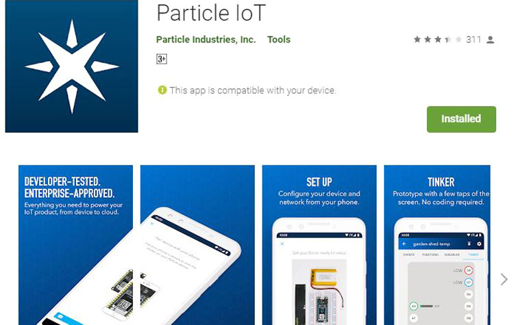
Before programming the Argon board, we have to configure it by using the Android or iOS Particle app. So, download this app and make sure you have a working internet connection so that the Argon board can make a connection with it.
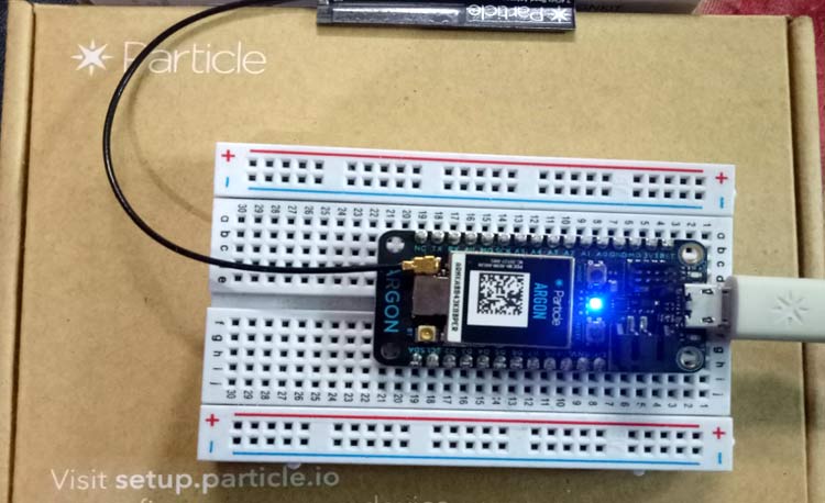
1. Now, plug the Argon board with the laptop or any USB power supply with the help of provided micro-USB cable. You will see the blue LED is blinking (Listening mode). If it is not blinking blue, hold the MODE button for 3 seconds, until the RGB led becomes blinking blue. To know more about the meaning of different LED status, please visit this documentation from Particle IO.
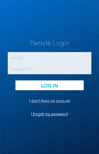
2. Open the Particle IoT app on your phone and make an account if you don’t have one or log in with your Particle credentials.
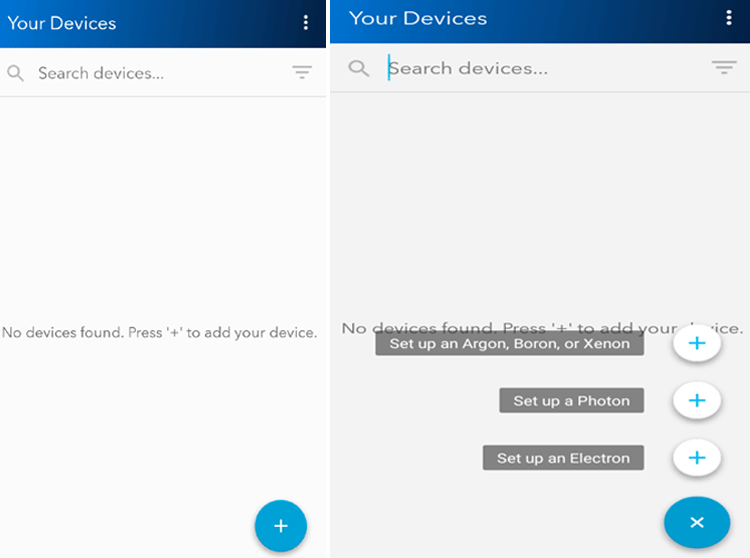
3. Now, to add our Argon device, press on the “+” button to add the device. Again press “+” in front of Set up Argon, Boron or xenon.
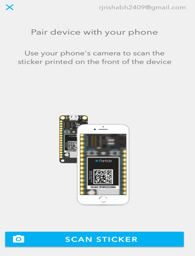
4. To communicate with the app, Argon uses Bluetooth so it will ask to enable Bluetooth on the smartphone. Now, scan the QR-code printed on your Argon board to connect the device with the smartphone.
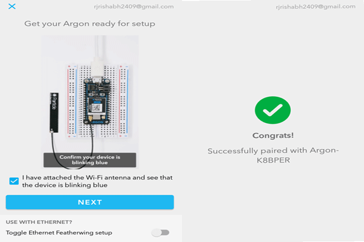
5. Next, it will ask whether you have connected the antenna or not. If you have connected the antenna, tick mark in the box and click on Next. Now, it will be successfully paired with the phone.
6. Next, it will ask to connect with the Mesh network. As we are not using Mesh so press on Do not have mesh network and click on Next.
Now, we have to send the credentials of the Wi-Fi network to the Argon. In the app, it will scan for the Wi-Fi networks, then choose your network and enter the password. After that, your Argon board will be successfully connected to the Particle Cloud and you will see Cyan color is blinking slowly on your board.
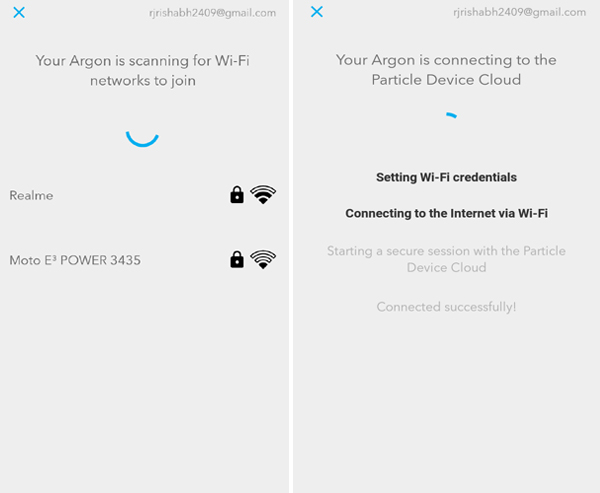
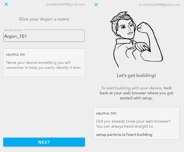
7. Now, give the name to your Argon board. Enter any name of your choice and click on Next.
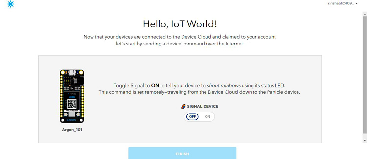
8. Open the web browser on the laptop and enter the link setup.particle.io?start-building. Now, we are almost done with the setup. To verify that our Argon is successfully connected with the cloud, Click on the Signal Device button. It will blink the rainbow colors on the Argon LED.
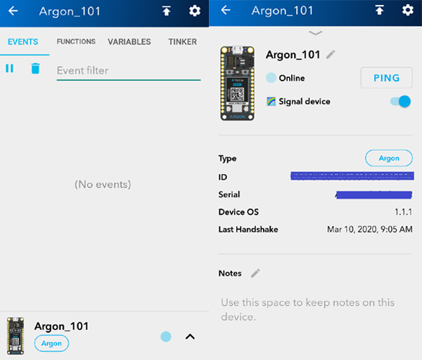
9. You can Signal your device using the app. Click on the name of your board and open the device as shown below. You will see that the Argon board is online. On the next screen, you will find the Signal button.
10. Now, we are all set to program the Argon board using a web IDE.
Programming Argon board using Web IDE
1. Go to Particle Console and log in with the credentials that you have login within Particle App.

2. As you can see there are many options on the left part of the screen which include adding new devices, creating mesh networks, Integration with IFTTT, Microsoft Azure and Web IDE. Also, you can see your device listed on the screen.
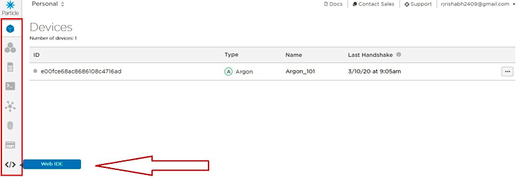
3. First, click on the Web IDE option. A new tab will open with online IDE as shown below. On this IDE, there will be libraries for different sensors and boards with some example code. If you are familiar with Arduino IDE, you will find it very easy and its programming structure is the same as Arduino IDE.
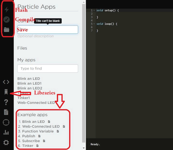
4. We will use a very basic example code to Blink an LED. So, click on that example code.
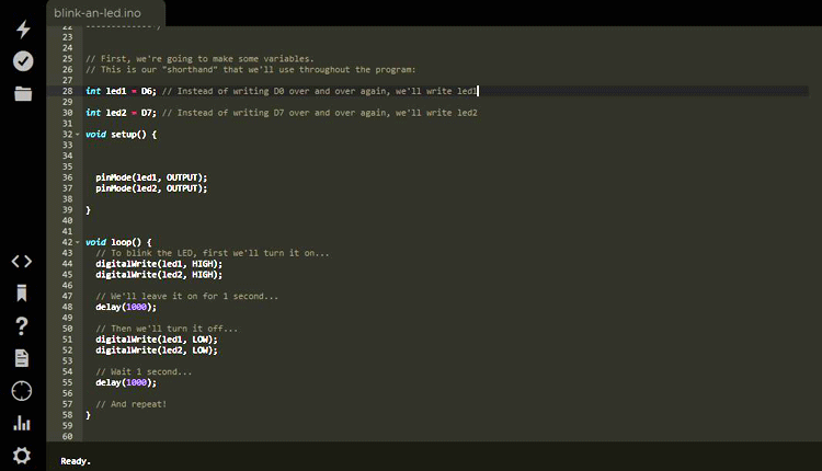
5. The basic structure is the same as Arduino IDE, use void setup and void loop function to write the code.
Now, declare two variables for two LEDs.
int led1 = D6;
int led2 = D7;
6. In void setup(), set the pin mode as output using pinMode() function for both the LEDs.
void setup() {
  pinMode(led1, OUTPUT);
  pinMode(led2, OUTPUT);
}
7. In void loop(), use digitalWrite() function to make the LEDs turn on and off as shown below.
void loop() {
digitalWrite(led1, HIGH);
digitalWrite(led2, HIGH);
delay(1000);
digitalWrite(led1, LOW);
digitalWrite(led2, LOW);
delay(1000);
}
Complete code with a demonstration video is given at the end of this tutorial. Now, compile this code by clicking on the Verify button on the top left section.

If there is no error in the code, you will find the Code verified message on the bottom of the screen.
Now, the code is ready to be flash in the Argon board. Make sure you have connected the board to the laptop or any other power supply and also it is connected to the internet. RGB LED should blink cyan color slowly, which means that your board is connected to the particle cloud.
Now, Flash the code by clicking on the flash button on the top left corner. It should show a message Flash successful on the screen as shown below. To see it in action, connect two LEDs at pin D6 and D7 and reset the board.
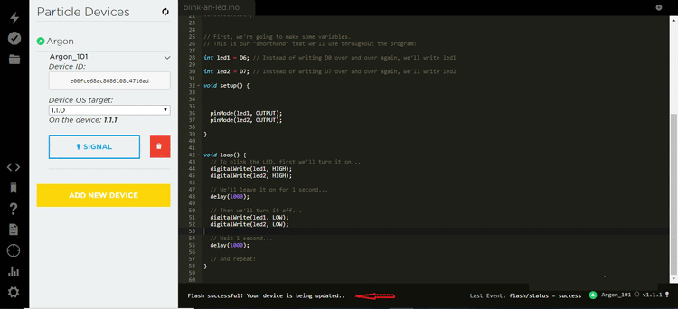
In this way, you can write your own code and can upload using OTA functionality and make your project more smart.
Using Tinker Functionality on Argon Development Board
There is one special code example in the web IDE called Tinker. After uploading this code in Argon board, you can control many pins at a time without hard coding it. Also, you can get sensor readings without specifying the pins in the code.
1. As soon as after flashing the Tinker example code, you will see the Tinker option is enabled in the Argon device option as shown. Click on the Tinker option.
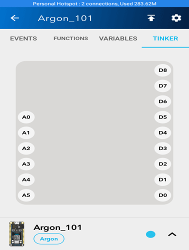
2. Now, choose the pin on which you want to get output or input. On clicking, you will be asked to click on digitalWrite, digitalRead, analogRead and analogWrite. In our case, click on digitalWrite on pin D7 and D6.
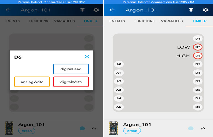
After assigning the function, just click on pin D7 or D6, the LED will glow. On pressing D7 again the LED will turn off. Similarly, you can get the sensor data on different pins and can control the appliances at the same time.
You can try all the example codes for a better understanding of different functionalities of the board.
Apart from using an online IDE, you can download the Particle Desktop IDE and Workbench where you can write code and flash in the same way as an online IDE. But these IDEs are also online development software. For more information about the Particle cloud, you can check its official documentation here.
Complete code with a Demonstration Video is given below.
Complete Project Code
int led1 = D6; // Instead of writing D0 over and over again, we'll write led1
int led2 = D7; // Instead of writing D7 over and over again, we'll write led2
void setup() {
  pinMode(led1, OUTPUT);
  pinMode(led2, OUTPUT);
}
void loop() {
  // To blink the LED, first we'll turn it on...
  digitalWrite(led1, HIGH);
  digitalWrite(led2, HIGH);
  // We'll leave it on for 1 second...
  delay(1000);
  // Then we'll turn it off...
  digitalWrite(led1, LOW);
  digitalWrite(led2, LOW);
  // Wait 1 second...
  delay(1000);
  // And repeat!
}
TINKER CODE
/* Function prototypes -------------------------------------------------------*/
int tinkerDigitalRead(String pin);
int tinkerDigitalWrite(String command);
int tinkerAnalogRead(String pin);
int tinkerAnalogWrite(String command);
/* This function is called once at start up ----------------------------------*/
void setup()
{
//Setup the Tinker application here
//Register all the Tinker functions
Particle.function("digitalread", tinkerDigitalRead);
Particle.function("digitalwrite", tinkerDigitalWrite);
Particle.function("analogread", tinkerAnalogRead);
Particle.function("analogwrite", tinkerAnalogWrite);
}
/* This function loops forever --------------------------------------------*/
void loop()
{
//This will run in a loop
}
/*******************************************************************************
 * Function Name  : tinkerDigitalRead
 * Description    : Reads the digital value of a given pin
 * Input          : Pin
 * Output         : None.
 * Return         : Value of the pin (0 or 1) in INT type
                    Returns a negative number on failure
 *******************************************************************************/
int tinkerDigitalRead(String pin)
{
//convert ascii to integer
int pinNumber = pin.charAt(1) - '0';
//Sanity check to see if the pin numbers are within limits
if (pinNumber< 0 || pinNumber >7) return -1;
if(pin.startsWith("D"))
{
pinMode(pinNumber, INPUT_PULLDOWN);
return digitalRead(pinNumber);
}
else if (pin.startsWith("A"))
{
pinMode(pinNumber+10, INPUT_PULLDOWN);
return digitalRead(pinNumber+10);
}
return -2;
}
/*******************************************************************************
 * Function Name  : tinkerDigitalWrite
 * Description    : Sets the specified pin HIGH or LOW
 * Input          : Pin and value
 * Output         : None.
 * Return         : 1 on success and a negative number on failure
 *******************************************************************************/
int tinkerDigitalWrite(String command)
{
bool value = 0;
//convert ascii to integer
int pinNumber = command.charAt(1) - '0';
//Sanity check to see if the pin numbers are within limits
if (pinNumber< 0 || pinNumber >7) return -1;
if(command.substring(3,7) == "HIGH") value = 1;
else if(command.substring(3,6) == "LOW") value = 0;
else return -2;
if(command.startsWith("D"))
{
pinMode(pinNumber, OUTPUT);
digitalWrite(pinNumber, value);
return 1;
}
else if(command.startsWith("A"))
{
pinMode(pinNumber+10, OUTPUT);
digitalWrite(pinNumber+10, value);
return 1;
}
else return -3;
}
/*******************************************************************************
 * Function Name  : tinkerAnalogRead
 * Description    : Reads the analog value of a pin
 * Input          : Pin
 * Output         : None.
 * Return         : Returns the analog value in INT type (0 to 4095)
                    Returns a negative number on failure
 *******************************************************************************/
int tinkerAnalogRead(String pin)
{
//convert ascii to integer
int pinNumber = pin.charAt(1) - '0';
//Sanity check to see if the pin numbers are within limits
if (pinNumber< 0 || pinNumber >7) return -1;
if(pin.startsWith("D"))
{
return -3;
}
else if (pin.startsWith("A"))
{
return analogRead(pinNumber+10);
}
return -2;
}
/*******************************************************************************
 * Function Name  : tinkerAnalogWrite
 * Description    : Writes an analog value (PWM) to the specified pin
 * Input          : Pin and Value (0 to 255)
 * Output         : None.
 * Return         : 1 on success and a negative number on failure
 *******************************************************************************/
int tinkerAnalogWrite(String command)
{
//convert ascii to integer
int pinNumber = command.charAt(1) - '0';
//Sanity check to see if the pin numbers are within limits
if (pinNumber< 0 || pinNumber >7) return -1;
String value = command.substring(3);
if(command.startsWith("D"))
{
pinMode(pinNumber, OUTPUT);
analogWrite(pinNumber, value.toInt());
return 1;
}
else if(command.startsWith("A"))
{
pinMode(pinNumber+10, OUTPUT);
analogWrite(pinNumber+10, value.toInt());
return 1;
}
else return -2;
}

