When you take your phone in sunshine or in high lighting, then it automatically adjusts the brightness according to the lighting conditions. Most of the display devices now a days, whether it’s a TV or mobile phone, have the Ambient Light Sensor inside to adjust the brightness automatically. Today in this tutorial, we will use one such sensor BH1750 Light Sensor Module and interface it with Arduino and show the Lux value over 16x2 LCD.
Introduction to BH1750 Digital Light Sensor Module
BH1750 is a Digital Ambient Light Sensor or a Light Intensity Sensor, which can be used to auto adjust the brightness of display in mobiles, LCD displays, or to turn on/off the headlights in cars based upon the outdoor lighting conditions.
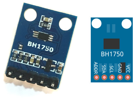
The sensor uses I2C serial communication protocol which makes it easier to use with microcontrollers. For I2C communication it has SDI and SDA pins. The pinout of BH1750 Ambient Light Sensor is shown below:

The output of this sensor is in LUX (lx), so it does not require any further calculations. Lux is the unit to measure Light intensity. It measures the intensity according to the amount of light hitting on a particular area. One lux is equal to to one lumen per square meter.
The sensor operates on voltages from 2.4V to 3.6V (typically 3.0V) and it consumes current of 0.12mA. This sensor has a wide range and high resolution (1-65535lx) and in addition, the measurement variation is also small (about +/-20%). It can also work independently without any external component.
Although a LDR sensor can also be used to control the devices based on lighting conditions but its not that accurate. We have used LDR sensor to build many light controlled applications:
- Arduino Light Sensor Circuit using LDR
- Dark Detector using LDR and 555 Timer IC
- Simple LDR Circuit to Detect Light
- Arduino Color Mixing Lamp using RGB LED and LDR
Arduino BH1750 Ambient Light Sensor Circuit Diagram
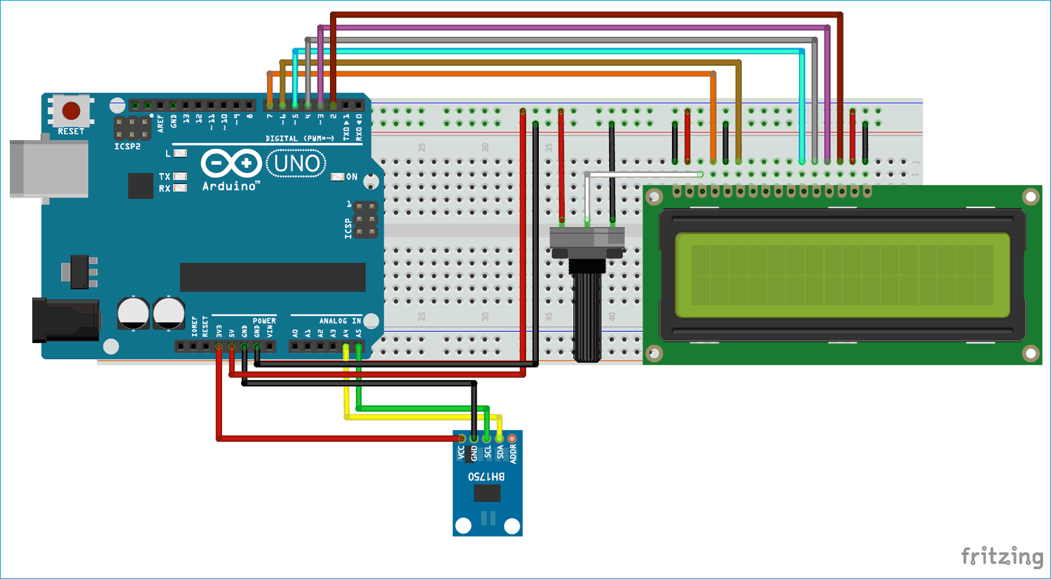
The circuit diagram to connect BH1750 Light sensor with Arduino is shown below.
I2C communication pins SDA and SCL of BH1750 are connected to Arduino pin A4 and A5 respectively for I2C communication. As we know the operating voltage for the sensor is 3.3v so VCC and GND of BH1750 are connected to 3.3V and GND of Arduino. For LCD, data pins (D4-D7) are connected to digital pins D2-D5 of Arduino and RS and EN pins are connected to D6 and D7 of Arduino. V0 of LCD is connected to pot and a 10k pot is used to control the brightness of LCD.

Programming Arduino for interfacing BH1750 Light Sensor
The programming portion for using this LUX sensor with Arduino is very easy. Although there is a library available for this sensor, but we can also use it without that.
Firstly, we’ve included header files for LCD and I2C protocol.
#include<Wire.h>
#include<LiquidCrystal.h>
In setup function, we’ve initialized both LCD and sensor and printed the opening message on LCD.
void setup()
{
  Wire.begin();
  lcd.begin(16,2);
  lcd.print("  BH1750 Light  ");
  lcd.setCursor(0,1);
  lcd.print("Intensity Sensor");
  delay(2000);
}
Here BH1750_Read and BH1750_Init functions are used to read and write the Lux values respectively. The Wire.beginTransmission() function is used to begin the transmission and Wire.requestFrom(address, 2) function is used to read registers where 2 indicates the number of registers.
Further Wire.endTransmission() is used to end the transmission and Wire.write() function is used to go to the desired register by entering the address of that register in it.
int BH1750_Read(int address)
{
  int i=0;
  Wire.beginTransmission(address);
  Wire.requestFrom(address, 2);
  while(Wire.available())
  {
    buff[i] = Wire.read();
    i++;
  }
  Wire.endTransmission();
  return i;
}

void BH1750_Init(int address)
{
  Wire.beginTransmission(address);
  Wire.write(0x10);
  Wire.endTransmission();
}
In loop function, we are printing the real time lux values over LCD. First compare the return value from BH1750_Read function with 2, and then start printing the Lux values if it is equal to 2. Here the values are compared with 2 because BH1750_Read function returns the value of register count and we are reading only 2 registers. So when it reaches to 2, the program starts printing the LUX values of light intensity.
Then a formula is used to get the values from both the registers and divide them by 1.2, which is the measurement accuracy.
void loop()
{
  int i;
  uint16_t value=0;
  BH1750_Init(BH1750address);
  delay(200);

  if(2==BH1750_Read(BH1750address))
  {
    value=((buff[0]<<8)|buff[1])/1.2;
    lcd.clear();
    lcd.print("Intensity in LUX");
    lcd.setCursor(6,1);
    lcd.print(value);
  }
  delay(150);
}
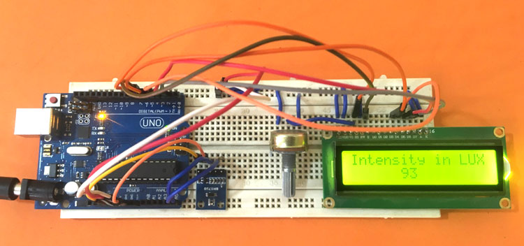
Finally power up the Arduino and upload the program into Arduino. As soon as program is uploaded the LCD starts showing the light intensity in LUX units. You can also vary the values by changing the light intensity around the sensor as demonstrated in the Video below.
Complete Project Code
#include<Wire.h>
#include<LiquidCrystal.h>
int BH1750address = 0x23;
byte buff[2];
LiquidCrystal lcd (7,6,5,4,3,2); //RS, E, D4, D5, D6, D7
void setup()
{
  Wire.begin();
  //Serial.begin(9600);
  lcd.begin(16,2);
  lcd.print("  BH1750 Light  ");
  lcd.setCursor(0,1);
  lcd.print("Intensity Sensor");
  delay(2000);
}
void loop()
{
  int i;
  uint16_t value=0;
  BH1750_Init(BH1750address);
  delay(200);
  if(2==BH1750_Read(BH1750address))
  {
    value=((buff[0]<<8)|buff[1])/1.2;
    lcd.clear();
    lcd.print("Intensity in LUX");
    lcd.setCursor(6,1);
    lcd.print(value);
    //Serial.print(val);
    //Serial.println("[lux]");
  }
  delay(150);
}
int BH1750_Read(int address)
{
  int i=0;
  Wire.beginTransmission(address);
  Wire.requestFrom(address, 2);
  while(Wire.available())
  {
    buff[i] = Wire.read();
    i++;
  }
  Wire.endTransmission();
  return i;
}
void BH1750_Init(int address)
{
  Wire.beginTransmission(address);
  Wire.write(0x10);
  Wire.endTransmission();
}


