If you are thinking about building yourself a burglar alarm or you are thinking about Automating lights in your room, then you should definitely consider using an HC-SR501 Passive Infrared Sensor or PIR sensor for your project, because as the name suggests a PIR sensor allows you to detect when a person or animal moves in or out from the range of your sensor. And you can find this sensor in many modern day ready made security systems. So in this article, we decided to interface the popular HC-SR501 with ESP32 and in the process, we will let you know all the details about it. So without further ado let's get right into it. Also find links, to interface PIR sensor with other microcontrollers, at the end of this article.
How does a PIR sensor work?
Every object above absolute zero (0 Kelvin / -273.5 *C) emits heat energy, in the form of infrared radiation. The hotter the object is, the more radiation it emits. The radiation is not visible to the human eye and the PIR sensor is specifically designed to detect such levels of radiation.
A PIR sensor is made out of two main parts
- A pyroelectric sensor, which you can see in the image below, is round with a rectangular crystal in the center.
- A special lens called a fresnel lens which focuses the infrared signals on the pyroelectric sensor.
Pyroelectric Sensor
A pyroelectric sensor consists of a window with two rectangular slots made out of coated silicon, that allows IR rays to pass through and blocks any other radiation. The sensors are designed so that one cancels the other, this is so that the sensor can cancel out the ambient radiation and detect changes in the radiation pattern.
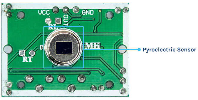
When there is no movement detected, the resulting output signal is zero, because the sensor is detecting background radiation. But when any one half of the sensor intercepts a movement causes changes in voltage level between two parts of the sensor and this is how motion is detected.
Fresnel Lens
A Fresnel lens consists of a series of concentric grooves carved into the plastic. These contours act as individual refracting surfaces, gathering parallel light rays at a focal point. As a result, a Fresnel lens is able to focus light similarly to a conventional optical lens.

In reality, to increase the range and field of view of the PIR sensor, the lens is divided into several facet sections, each section of which is a separate Fresnel lens. You can learn more about PIR sensor here.
HC-SR501 PIR Motion Sensor Module Pinout
The HC-SR501 module has three pins. The silkscreen of the module is hidden by the Fresnel lens, so refer to the following pinout given below. Apply power 5V – 12V and ground, the sensor output goes HIGH when motion is detected and goes LOW when idle (no motion detected).
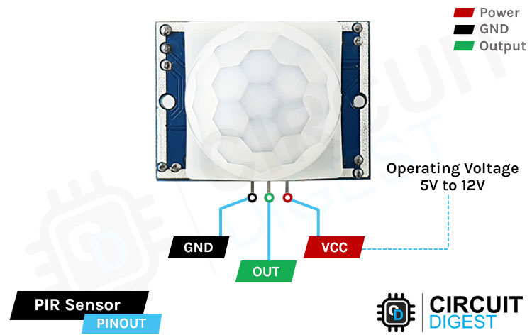
VCC is the power pin of the sensor. This pin supports input of 4.5V to 12 volts, but normally 5V supply is used to supply the PIR sensor.
Out is the output pin of the PIR sensor module. It has a 3.3V logic level so it goes high when motion is detected, and goes low when no motion is detected.
GND is the Ground pin of the module, connect it to the supply ground in your circuit.
HC-SR501 PIR Sensor Module Onboard Parts
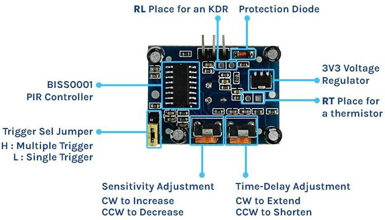
The HC-SR501 sensor consists of various components, and the parts marking of the PIR sensor module is shown below.
BISS0001 PIR Controller
At the heart of the module, we have a BIS0001 PIR controller. Because of its noise characteristic, it's one of the most stable PIR controllers available. This chip takes the raw data from the sensor and processes it to get digital output. More information about the IC is available on its datasheet.
Trigger Selection Jumper
There are two trigger modes that determine how the sensor will react when motion is detected.
- Single Trigger Mode: The constant motion will cause a single trigger.
- Multiple Trigger Mode: The constant motion will cause a series of triggers.
L- In this setting the sensor will be in single trigger mode, in this mode the output goes high when motion is detected. And remains high for a certain period of time which is set by the time delay potentiometer. Any other type of detection is blocked until the output goes low.
H- Selecting these settings will set the multi trigger mode. In this mode the output goes high as motion is detected and the high period is determined by the set potentiometer. But unlike single trigger mode further detection is not blocked and it can be continuously triggered, the pin goes to low when no movement is detected.
Sensitivity Adjustment
The PIR sensor has a potentiometer on the back to adjust the sensitivity. With the help of the potentiometer the sensitivity of the device can be adjusted. Rotating the pot clockwise increases the sensitivity and rotating the pot counterclockwise decreases the sensitivity.
Time-Delay Adjustment
The other pot on the back of the sensor sets how long the output will remain high and after the motion is detected Turning the pot clockwise increases the delay, and turning the pot counter-clockwise decreases the delay.
RT and RL (Thermistor and LDR)
The HC-SR501 PIR sensor has two optional solder pads for components, these are usually leveled as RT and RL.
The RT is for an additional thermistor or temperature sensitive resistor. Adding this will allow the HC-SR501 to be used in extreme temperatures. This also increases the accuracy of the detector.
The RL is for connecting light dependent resistors. Adding this component will allow the HC-SR501 to operate in the dark.
3.3V Voltage Regulator
The module comes with a 3.3V voltage regulator so it can be powered by 4.5V to 12V power supply. although 5V is commonly used.
Protection Diode
The module comes with a protection diode to protect the diode from reverse voltage and current.
HC-SR501 PIR Sensor with ESP32 - Circuit Diagram
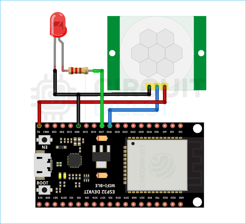
Now we have a clear idea about how a PIR sensor works we can start connecting all the required wires to the ESP32. Connecting the PIR sensor to ESP32 is really simple. You need to connect the power pins to the 5V pin and the ground pin of the ESP32. The operating voltage of the PIR sensor is 4.5V to 12V so we need to power the HC-SR501 with the +5V pin of the ESP32.
Commonly Asked Questions on HC-SR501 PIR Sensor
How do I adjust the sensitivity on my PIR sensor?
You can use the Sensitivity Adjust knob of the PIR sensor. The sensitivity adjustment knob determines the distance of motion detection of the sensor. It can be made to vary between 3 meters and 7 meters.
What are the disadvantages of PIR sensors?
They have lower sensitivity and less coverage compared to microwave sensors. They do not operate above 35 degree C. It works effectively in LOS (Line of Sight) and will have problems in the corner regions. It is insensitive to the very slow motion of the objects.
Why do PIR sensors fail?
The main reasons why a PIR sensor stops working are: The PIR sensor is faulty. The lens of the PIR is covered up (for example, the internal plastic lens cover has moved) Wires have come loose inside the sensor or have not been terminated properly.
Code for Interfacing Motion sensor with ESP32
The code for the HC-SR501 is very simple and on top of that it does not require any library to work with. As we all know, the pin of the PIR sensor goes low when motion is detected by the PIR sensor. The ESP32 code just keeps track of whether the pin is LOW or high, and prints a message to the serial monitor window accordingly.
We start our code by defining all the required variables in which we have defined the ledpin, the ir_sesnor_input pin.
int ledPin = 25;      // choose the pin for the LED
int inputPin = 26;     // choose the input pin (for PIR sensor)
Next, we have our setup function, in this function, we set the pin status of the pir sensor pin and the led pin as output and we also enable the serial monitor to print debug statements.
void setup() {
  pinMode(ledPin, OUTPUT);      // declare LED as output
  pinMode(inputPin, INPUT);     // declare sensor as input
  Serial.begin(9600);
}
Next, we have our loop function, in the void loop() function we read the input pin of the sensor and check if the pin is high or not. If the pin is high we turn on the LED and print motion detected messages on the serial monitor window.
  if (val == HIGH)  // check if the input is HIGH
  {
    digitalWrite(ledPin, HIGH);  // turn LED ON
     if (pirState == LOW) {
      Serial.println("Motion detected!"); // print on output change
      pirState = HIGH;
    }
  }
Now in the else statement we set the pin low and turn off the LED attached to the sensor pin and we print a message that motion detection has ended.
else {
    digitalWrite(ledPin, LOW);
    if (pirState == HIGH) {
      Serial.println("Motion Detection ended!");
      pirState = LOW;
    }
  }
}
Working of HC-SR501 Module with ESP32
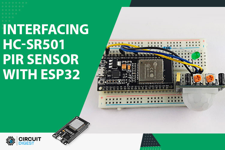
The video below shows the hardware circuit of the PIR sensor, as you can see we have connected the PIR sensor and the LED according to the schematic shown above. We have also programmed the ESP32 so that when the sensor detects any movement the LED on the breadboard lights up and as you can see from the GIF below the LED lights up as soon as I move my hand in front of the sensor, and for this test we have set the detect range of the sensor to minimum so that it cannot the detect the movement on the room.
Troubleshooting HC-SR501 PIR Sensor Module
There could be a couple of reasons why the PIR sensor could not work properly. You need to go through some tests to figure out the root cause of the issue.
- The operating voltage of the sensor is 4.8V to 20V so powering the sensor with 3.3V will not work.
- In some cases you can see dust buildup on top of the lens so for that reason the PIR sensor could stop working.
- In some cases the dust buildup can happen inside the sensor and that can be the reason that the sensor is not working.
- If none of the above mentioned methods work then try rotating the potentiometer. If you have set the sensitivity of your potentiometer to minimum then that could be the reason that your sensor is not working.
- After testing all the methods, if the sensor does not work then you can be sure you have a faulty sensor in your hand.
Project Using HC-SR501 PIR Sensor Module and ESP32
Dog Barking Security Alarm using Arduino, PIR Sensor and Dog Barking Sound Module
If you have some HC-SR501 PIR sensor lying around and you are looking for some interesting project to built with those, then this may be the project you are looking for because in this project we have produced dog barking sound with the help of an Arduino and we are using a HC-SER501 to build a security system with the PIR sensor.
Motion Detector Using MSP430 Launchpad and PIR Sensor
If you want to learn how to Interface a PIR Sensor with MSP430 Launchpad then this project is for you, because in this project we have interfaced the HC-SR501 PIR sensor with MSP430 launchpad to build a simple Motion Detection Alarm.
Raspberry Pi Motion Sensor Alarm
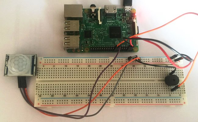
In this project we have shown you how you can interface HC-SR501 motion sensors with Raspberry Pi, and in the process, we have built a Pi based motion alarm.
Interfacing PIR Sensor with PIC Microcontroller
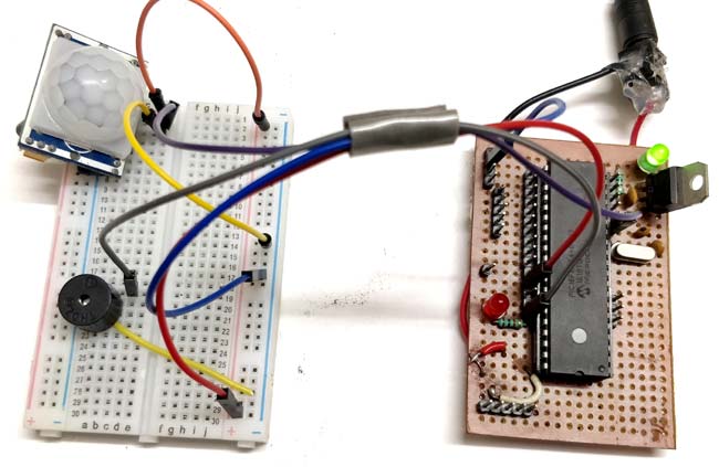
If you are looking for how to interface an HC-SR501 PIR sensor with a PIC microcontroller then this project is for you, because in this project we have interfaced a PIC microcontroller with HC-SR501 sensor to build a simple alarm system.
IoT based Security System with Voice Message Using ESP8266
If you are looking for some interesting project on the internet then this project is for you because in this project we have used a PIR sensor in conjunction with a buzzer to build an Email based security system that can trigger an Email when it detects someone.
Complete Project Code
int ledPin = 25;
int inputPin = 26;
int pirState = LOW;
int val = 0;
void setup() {
  pinMode(ledPin, OUTPUT);
  pinMode(inputPin, INPUT);
  Serial.begin(9600);
}
void loop(){
  val = digitalRead(inputPin);
  if (val == HIGH)
  {
    digitalWrite(ledPin, HIGH);
    if (pirState == LOW)
  {
      Serial.println("Motion detected!");
      pirState = HIGH;
    }
  }
  else
  {
    digitalWrite(ledPin, LOW);
    if (pirState == HIGH)
  {
      Serial.println("Motion Detection ended!");
      pirState = LOW;
    }
  }
}
