If you are planning on building a robot with DC motors then you will eventually learn that you need to control both the speed and direction of the motor if you want it to move it in a certain direction. And one of the best ways to do it is by using a L293D motor driver IC, because it's cheap, easy to use and with a bit of PWM support it can control both speed and direction. Which is why in this tutorial we will be using the popular L293D motor driver IC to simple control the speed and direction of the motor. In our previous project we have built many projects with L293D motor drive IC like RF Controlled Robot, Automatic Door Opener using Arduino, and Interfacing Stepper Motor with AVR Microcontroller Atmega16 you can check those out if you are interested in those topic.
Update: The L293D ICs are quick being replaced but the L298N IC mainly because of the same cost and better performance provided by the L298N ICs, you can also check out how to use L298N Motor Driver module with arduino to know more.
Controlling a DC Motor with Microcontroller
In order to get complete control of the motor we need to take control of the speed and direction of the motor, and to do that we need to use Pulse Width Modulation or PWM Technique to control the speed and we are going to use the internal H-bridge to control the direction of the motor.
PWM - Motor Speed Control
When we are talking about a DC motor to change the speed of the DC motor we need to change the amplitude of the input voltage that is applied to the motor. A common technique to do that is PWM (Pulse Width Modulation). In PWM the applied voltage is adjusted by sending a series of pulses so the output voltage is proportional pulse width generated by the microcontroller that is also known as duty cycle.
The higher the duty cycle, the higher the average voltage applied to the DC motor (resulting in higher speed) and the shorter the duty cycle, the lower the average voltage applied to the DC motor (resulting in lower speed).
H-Bridge motor Direction Control
To change the direction of rotation of a DC motor you need to change the polarity of the supply. A common technique to do that is by using an H-bridge motor driver. A H-bridge motor driver consist of four switches (usually MOSFETs) arranged in a certain formation and the motor is connected to the center of the arrangement to form the H-like structure
By Closing/enabling two opposite switches we can change the direction of the flowing current thus changing the direction of rotation.
L293D Motor Driver IC
The L293D is a dual channel motor driver IC capable of driving dual DC motors with bidirectional control and a single stepper motor. The L293D devices are quadruple high current half-H drivers. The L293D is designed to provide bidirectional drive currents of up to 600-mA at voltages from 4.5 V to 36 V. This IC is also designed to drive inductive loads such as relays, solenoids, DC and bipolar stepping motors also.
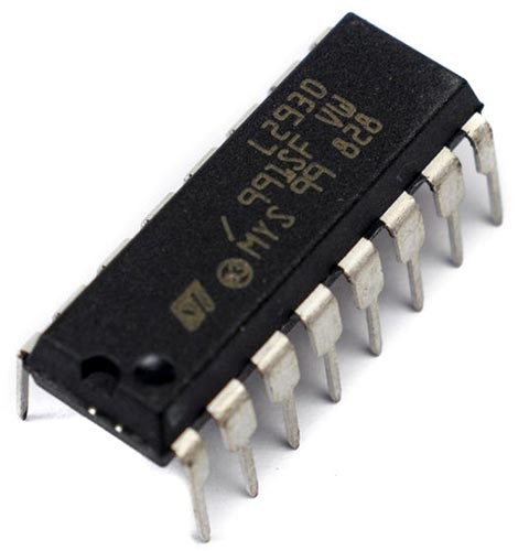
The L293D is most often used to drive motors but because of its totem pole output driver it can be used to drive solenoids, four uni-directional DC motors, two bi-directional DC motors or one stepper motor. For further information on this IC, you can check the datasheet of L293D IC. Follow the links to learn more about Motor driver ICs and L293D.
Note: Please Note that the L293 and L293D are two different variants, the L293 IC does not have the flyback diodes built in, so you need to add those in your circuit if you are using the L293 version. The L293D version has all the flyback diodes connected internally so for the L293D IC you don't need to connect external diodes.
L293D Motor Driver IC Pinout
The pinout of the L293d Motor Driver IC is shown below. The L293D has a total of 16 pins that can be connected to the microcontrollers and motor.
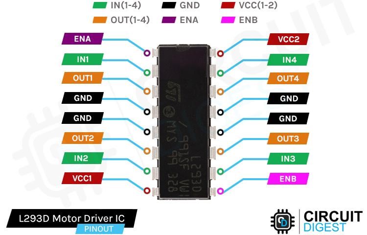
ENA, ENBPin1 and Pin9 of the IC are the ENA and ENB pins respectively. Pulling the pins high enables the motor and they start spinning. By pulling the pins low the motor stops rotating. By applying a PWM signal onto these pins we can control the speed of the DC motor.
IN1, IN2, IN3, IN4 This IC has two direction control pins for each channel IN1 and IN2 control the spinning direction of motor A. Where IN3 and IN4 control the spinning direction of motor B.
OUT1, OUT2, OUT3, OUT4 The L293D motor Driver IC has four output channels, the OUT1 and OUT2 can be used to control a single motor. The OUT3 and OUT can be used to control another motor. So, with this IC, you can control two 5 - 36V DC motors respectively. Each channel on the IC can drive up to 600mA.
GND Pins 4,5 and 12,13 are the ground pins of the IC this pin not only provides ground connection for the IC, but it also acts as a heat sink for the IC, if your design has this IC onboard you need to consider design recommendations provided by the datasheet of the device.
VCC1 This pin provides power to the internal motor driver of the IC. The VCC1 pin can be connected to 4.5V to 36V of supply.
VCC2 This pin is used to connect the internal logic circuit of the IC; you need to connect 5V to this pin.
Commonly Asked Questions on L293D Motor Driver IC
Why do we use L293D?
The L293D is designed to provide bidirectional drive currents of up to 600-mA at voltages from 4.5 V to 36 V. Both devices are designed to drive inductive loads such as relays, solenoids, DC and bipolar stepping motors, as well as other high-current/high-voltage loads in positive-supply applications.
How does an L293D work?
The L293D IC receives signals from the microprocessor and transmits the relative signal to the motors. It has two voltage pins, one of which is used to draw current for the working of the L293D and the other is used to apply voltage to the motor.
Can I connect 4 motors to L293D?
It is capable of driving four solenoids, four unidirectional DC motors, two bi-directional DC motors or one stepper motor. The L293D IC has a supply range of 4.5V to 36V and is capable of 1.2A peak output current per channel, so it works very well with most of our motors.
How many motors can be controlled by L293D?
The L293D is a 16-pin Motor Driver IC which can control up to two DC motors simultaneously, in any direction.
How does L293D control speed?
The L293D does not have any speed controlling capabilities. You need to use PWM from a microcontroller or any other source on the enable pin of the IC to control the speed of the motor.
Arduino and L293D Circuit Diagram
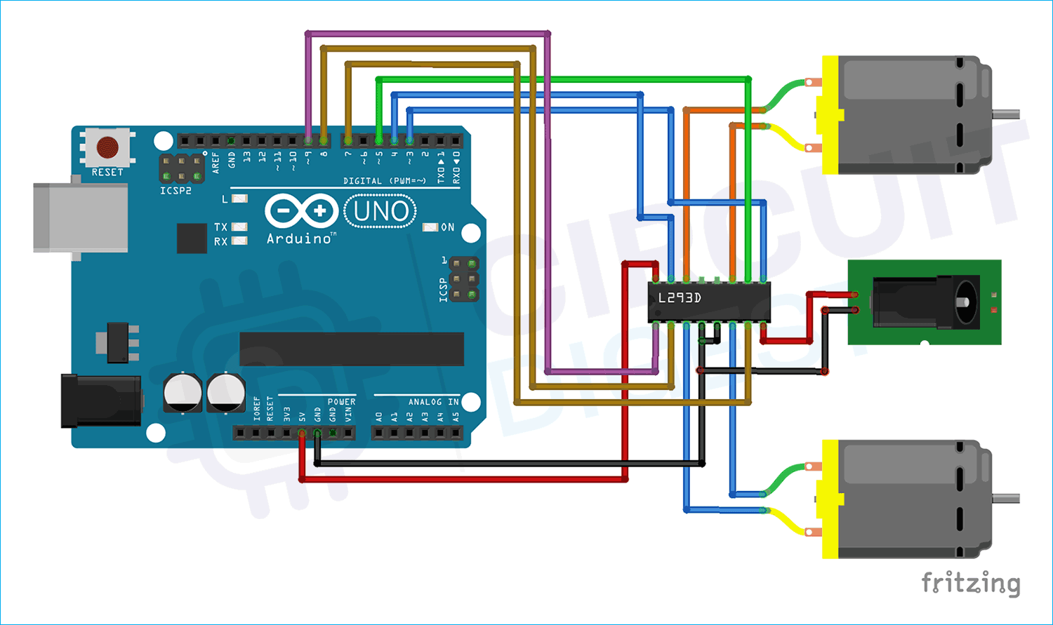
Now that we have completely understood how the L293D motor driver IC works we can connect all the required wires to the L293d Arduino, and we can write some code to rotate the motor and control the speed of the motor. Below is the circuit diagram for DC Motor with Arduino:
For our circuit we will be using a small 3V DC gear motor so we will be powering the IC with a 5V external power supply to the VCC1 pin of the IC. Now we need to connect 5V to the VCC2 pin of the IC which powers the internal logic circuit of the IC. Now we connect pin 9 and pin 3 to ENA and ENB pins of the Arduino, pins 9 and 3 are both PWM pins so we will be able to control the speed of the motor with Arduino. Now pins (8,7,5,4) are connected to IN1, IN2,IN3,and IN4 of the Arduino. Finally, the OUT1, OUT2, OUT3, and OUT4 pins are connected to the motor. When you are done you should have something that looks like the illustration shown below, but please note that for the sake of simplicity we have connected a single motor to the IC.
Arduino Code for Interfacing L293D Motor Driver IC with Arduino
The following sketch will give you a complete understanding on how to control the speed and direction of a DC motor with L293D IC.
The code for the Arduino is straight forward, first we have defined all the pins which are conned to the Arduino
// Motor A connections
int ENA= 9;
int IN1= 8;
int IN2 = 7;
Next, we have our setup function, in the setup function, we have set the pins as output and we have also made the output pins low so we could avoid false triggering.
void setup()
{
  pinMode(ENA, OUTPUT); // Set ENA as OUTPUT
  pinMode(IN1, OUTPUT); // Set IN1 as OUTPUT
  pinMode(IN2, OUTPUT); // Set IN2 as OUTPUT

  digitalWrite(IN1, LOW); // Make the Arduino Pin 8 Low
  digitalWrite(IN2, LOW); // Make the Arduino Pin 7 Low
}
Next, we have our loop() function. In the loop function we have first enabled the motor by using the analogWrite() on pin ENA that we have previously defined. Next we make the IN1 pin high and IN2 pin LOW doing so will rotate the motor clockwise.
// Rotate Motor Clockwise for 4 Seconds
  analogWrite(ENA, 255); // Enable the L293D IC
  digitalWrite(IN1, HIGH); // Make PIN 8 of the Arduino High
  digitalWrite(IN2, LOW); // Make PIN 7 of the Arduino LOW
  delay(4000); // wait for 4 Sec
Next, we make the IN1 LOW and IN2 HIGH doing so will rotate the motor to the counter clockwise direction.
// Rotate Motor counter-Clockwise for 4 Seconds
  digitalWrite(IN1, LOW); // Make PIN 8 of the Arduino LOW
  digitalWrite(IN2, HIGH);// Make PIN 7 of the Arduino HIGH
  delay(4000);
Next, we make both the IN1 and IN2 pins low; this will stop the motor from rotating. And we also add another delay of 1 sec.
// Stop Rotating the Motor
  digitalWrite(IN1, LOW);
  digitalWrite(IN2, LOW);
  delay(1000);
Next, we again enable the motor in clockwise direction but we do it so that we can use PWM in the next instruction to change the motor speed and direction.
// Turn on motors
  digitalWrite(IN1, LOW);
  digitalWrite(IN2, HIGH);
Next, we accelerate the motor by applying a PWM signal to the ENA pin of the L293D IC.
// Accelerate from minimum to maximum speed
  for (int i = 0; i < 256; i++) {
    analogWrite(ENA, i);
    delay(20);
  }
Next, we declare the motor by changing the PWM signal from 100% duty cycle to 0%.
// Decelerate from maximum speed to minimum
  for (int i = 255; i >= 0; --i) {
    analogWrite(ENA, i);
    delay(20);
  }
Finally, we turn off the motor by making the IN1 and IN2 pin low and we add another delay of 1S
// Now turn off motors
  digitalWrite(IN1, LOW);
  digitalWrite(IN2, LOW);
  delay(1000);
Working of the L293D Motor Driver IC with Arduino
The GIF below shows how the hardware circuit works. We have made the code so that after a certain delay the motor will change its direction and after that the speed of the motor will change to show the working of the PWM functionality.
Problem Interfacing L293D with Arduino? Here what should you do
The most common problem that you can face is a power issue. The recommended operating voltage of the L293D motor driver is 4.5V to 36V so voltage less than that and the motor driver will not work and voltage more than 36V will certainly damage the device.
Another common issue found in the L293D is when you power up your L293D IC it starts rotating the motor or the IC heats up exponentially. This is a clear indication of a damaged IC and you should change the IC immediately.
The Logic pin of the L293D is +5V tolerant so voltage more than that will damage the device.
When working with L293D IC you need to consider motor winding resistance, if the motor winding resistance is low it will consume more current than its rated for and that can damage the device permanently.
Projects Using L293D Motor Driver IC and Arduino
DIY Raspberry Pi Motor Driver HAT
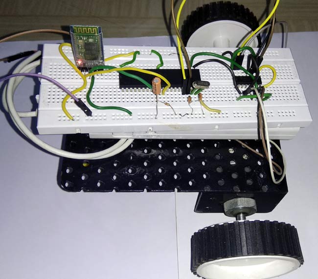
Looking for a cool little raspberry pi project online? Then search no more because in this project we have built a raspberry pi-based motor drive hat that can be used to drive any motor that consumes 1.5A peak current.
Android Controlled Robot using 8051 Microcontroller
Looking for a 8051 based motor controller which is easy to use and simple to make and cost less than any other microcontroller based solution, then you can check this project out, because in this project we have interfaced a 8051 microcontroller to build a PWM based motor driver system.
Mobile Phone Controlled Robot Car using G-Sensor and Arduino
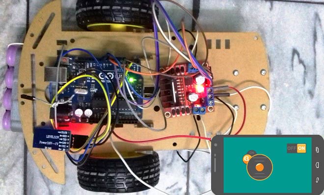
If you are looking to build a robot car then this project is for you, because in this project we have built an android phone and used it to drive a robot.
DIY Brushless Motor Using Fidget Spinner
If you are looking for some interesting projects online then this project is for you, because in this project we have used a BLDC motor to make a fidget spinner that can be used to understand how it works and how to interact with it.
Complete Project Code
// Motor A connections
int ENA = 9; // L293D Enable Pin
int IN1 = 8; // L293D IN1 Pin
int IN2 = 7; // L293D IN2 Pin
void setup()
{
  pinMode(ENA, OUTPUT); // Set ENA as OUTPUT
  pinMode(IN1, OUTPUT); // Set IN1 as OUTPUT
  pinMode(IN2, OUTPUT); // Set IN2 as OUTPUT
  digitalWrite(IN1, LOW); // Make the Arduino Pin 8 Low
  digitalWrite(IN2, LOW); // Make the Arduino Pin 7 Low
}
void loop() {
  // Rotate Motor Clockwise for 4 Seconds
  analogWrite(ENA, 255); // Enable the L293D IC
  digitalWrite(IN1, HIGH); // Make PIN 8 of the Arduino High
  digitalWrite(IN2, LOW); // Make PIN 7 of the Arduino LOW
  delay(4000); // wait for 4 Se
  // Rotate Motor counter-Clockwise for 4 Seconds
  digitalWrite(IN1, LOW); // Make PIN 8 of the Arduino LOW
  digitalWrite(IN2, HIGH);// Make PIN 7 of the Arduino HIGH
  delay(4000);
  // Stop Rotating the Motor
  digitalWrite(IN1, LOW);
  digitalWrite(IN2, LOW);
  delay(1000);
  // Turn on motors
  digitalWrite(IN1, LOW);
  digitalWrite(IN2, HIGH);
  // Accelerate from minimum to maximum speed
  for (int i = 0; i < 256; i++) {
    analogWrite(ENA, i);
    delay(20);
  }
  // Decelerate from maximum speed to minimum
  for (int i = 255; i >= 0; --i) {
    analogWrite(ENA, i);
    delay(20);
  }
  // Now turn off motors
  digitalWrite(IN1, LOW);
  digitalWrite(IN2, LOW);
  delay(1000);
}
