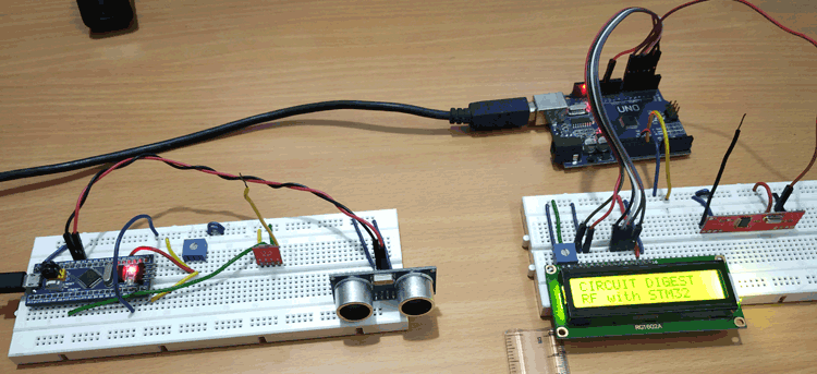
When it comes to giving your project wireless capabilities, the 433MHz ASK transmitter and receiver is a common choice among engineers, developers, and hobbyists because of its low price, easy to use libraries, and community support. So in this tutorial, we have decided to interface the 433MHZ ASK transmitter and receiver with Arduino and in the process we will let you know all the details about the module, how it works and the problems associated with the module. Previously we have built a few projects with ASK transmitter and receiver, those are RF Controlled Home Appliances, RF Transmitter and Receiver Circuit, and Interfacing 433Mhz RF Module with STM32F103C8.
You can check the above projects out if you want to learn more about the working of the 433MHz RF module and its working.
433MHz RF Transmitter and Receiver
The 433MHZ ASK Transceiver comes in a pair so in this section we will show the pinout for both the transmitter and receiver module.
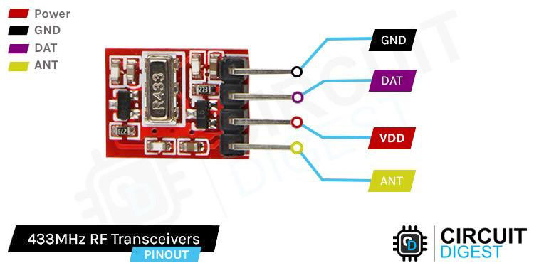
Data Pin accepts digital data to be transmitted.
VCC is the power pin of the module. The operating voltage of the device is 3.3V to 12V. Please do note that the range of the device is directly proportional to the supply voltage. Means providing more voltage can provide it with more range.
GND is the Ground pin of the RF Transmitter module.
ANT is the pin that connects to an external antenna. To improve the range you should shoulder a 17.3 -cm long solder wire to this pin.
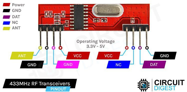
ANT Is the exposed pin that connects to the RF pin of the IC.
GND The first ground pin of the module.
GND The second ground pin of the module. Both the ground pins are internally linked so you can use any of them.
VCC Provides power to the 433MHz module. Unlike the transmitter, the receiver requires a 5V supply voltage.
VCC Provides power to the receiver module. The VCC pins are internally connected so you can use both of them.
NC Nothing is connected to this Pin of the receiver module.
Data This is the data out pin of the module. This pin outputs d
GND This is the third ground pin of the module. This pin is also internally conned to the all the ground pin.
How does A 433MHz RF Link Work?
As we have mentioned previously, this module uses Amplitude Shift Keying, modulation technique, to send digital data over radio frequency. In amplitude shift keying the amplitude of the carrier wave is modified depending on the input digital signal.
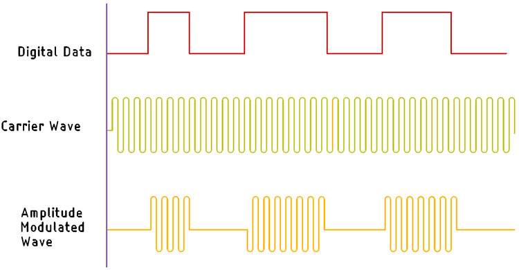
This modulation technique is very similar to Amplitude Modulation technique, because it uses two levels, for which sometimes it's referred to as a Binary Amplitude Shift Keying. The above schematic shows how the ASK transmission works. For logic 1 the carrier wave is transmitted, and for logic 0 no signal is transmitted.
The advantage of ASK over other techniques like FSK, and PSK is that the transmitter and the receiver circuit is very simple to implement and the manufacturing cost of this transmitter and receiver is very low. The disadvantage of ASK is that it is very susceptible to noise and interference because of its low operating frequency. The solution to this problem is to send data at a relatively low rate and do CRC checks on the software side of things.
Commonly Asked Questions on 433MHz RF Module
What is the range of 433 MHz RF modules?
Once you have connected a proper antenna and provided sufficient power to the 433MHz ASK Transmitter Module with Transmit Range up to 200m.
Why is 433 MHz so popular?
Power usage of 433 MHz devices is relatively low and comparable to other dedicated home automation standards like Z-Wave or Zigbee. This makes 433MHz also suitable for battery-operated devices like wireless sensors or buttons.
Do higher frequencies penetrate better?
Lower frequencies produce less resolution but have greater depth of penetration into the body; higher frequencies produce greater resolution, but depth of penetration is limited.
How do you check if an RF transmitter is working?
You should be able to make a small loop antenna ("sniffer") with a UHF diode and capacitor. Connect this to a voltmeter on DC and hold the loop close to the rf transmitter. You should see a hundred millivolts if it is transmitting.
Arduino and 433MHz RF Module Circuit Diagram
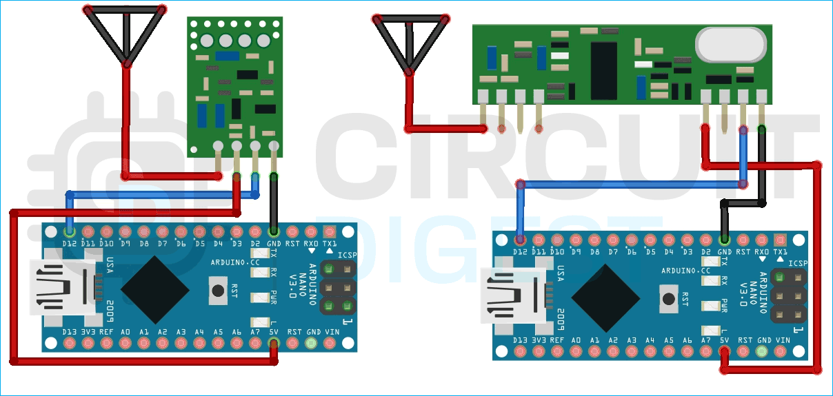
Circuit diagram for this Arduino transmitter and receiver is shown below. Connecting the Tx module to the 433MHz RF link is very simple. Connect the module's VCC pin to the 5V pin of the Arduino and connect the GND pin of the module to ground. The data pin should be connected to the pin D12 of the Arduino. Here at RF Transmitter side, we have used Arduino Nano.
Wiring the receiver module is also very simple, and once again you only need to make three connections. Connect the modules VCC and ground pins to the pins of the Arduino and connect the data out pin to pin D12 of the Arduino. For 433MHz RF receiver sider, we have used Arduino Pro mini. Any Arduino board can be used either of the side.
Note: The library internally uses the D12 pin as default so using the D12 pin would make the code very easy.
Arduino Code for Interfacing 433MHz ASK RF Link with Arduino
The code to establish the communication between the 433MHz RF link is very simple and easy to understand. We just need to include the RadioHead Library you can download the library from airspayce.com or by clicking the following link: Download RadioHead Library
Once you download the Zip file you need to install the library by navigating to Sketch > Include Library > Add.ZIP Library, and then you need to choose the Radiohead Library you just downloaded. Once that is done we can start our code.
RF Transmitter Code
We will start our code with the Arduino wireless transmitter. For transmitter we have used Arduino Nano, for that we need to include the RH_ASK.h which is the RadioHead library for ASK Transmitter. And we also need to include the SPI library as it is required by the RH_ASK.h library.
#include <RH_ASK.h>
#include <SPI.h> // Not actually used but needed to compile
Next we create an instance for the RK_ASK library and we name it driver.
RH_ASK driver;
Next we have defined a digital pin in which we have attached an LED. This LED will flicker for a second when data is received from the transmitter.
#define LED_PIN 2
Next, we have our setup function, in the setup function we first initialize the serial with 9600 baud and we check the driver.init() function to check if the transmitter is available or not. Next, we make the LED_PIN as output and that's it for the setup function.
void setup() {
  Serial.begin(9600);    // Debugging only
  if (!driver.init())
    Serial.println("init failed");
 }
Next, we have the loop() function, in the loop function, we make a character pointer called *msg and we pass the Hello World! String and we finally send the message with the help of the driver.send((uint8_t *)msg, strlen(msg)) function. And we weight for a delay of 200 ms
void loop() {
  const char *msg = "Hello World!";
  driver.send((uint8_t *)msg, strlen(msg));
  driver.waitPacketSent();
  delay(200);
}
RF Receiver Code
The code for Arduino Pro Mini at the receiver is exactly the same as the transmitter with some additional changes. We start of our code by including all the required libraries just like before
#include <RH_ASK.h>
#include <SPI.h> // Not actually used but needed to compile
Now we define a LED pin and we create an instance for the RH ASK module.
#define LED_PIN 2
RH_ASK driver;
Next we have the Void Setup() function, in the setup function we initialize the serial, to check if the receiver is working correctly or not and we also set the LED pin as output.
void setup() {
  Serial.begin(9600);    // Debugging only
  if (!driver.init())
    Serial.println("init failed");
  pinMode(LED_PIN, OUTPUT);
}
Next we have our void loop() function, in the loop function we define some array to hold and process the received data.
void loop() {
  uint8_t buf[RH_ASK_MAX_MESSAGE_LEN];
  uint8_t buflen = sizeof(buf);
  if (driver.recv(buf, &buflen)) // Non-blocking  {
    int i;
    driver.printBuffer("Got:", buf, buflen); // Message with a good checksum received, dump it.
  }
}
This marks the end of the code portion, and we can move to the next portion of the article.
Working of the Arduino RF Transmitter and Receiver Project
The video below shows how the hardware circuit works. We have configured the two Arduinos so that the Transmitter Arduino will send TX packets and receiver Arduino will show that in the serial monitor window, we have also programmed it so that when data is received by the Receiver an LED will flicker to notify that the message was received.
Error in Interfacing 433MHz ASK Transceivers Here is what you Should do
Check the data line and pin definition on the code. Sometimes libraries will use predefined pins for the library and that can mess up the code.
If you are having trouble working with the 433MHz module, you first need to check your power lines as mentioned earlier the operating voltage of the device is 3.3V to 5V. If the voltage is more or less than that, the module will not work, or it has a chance of getting damaged.
There could be an issue with the library that you are using. Check the IC properly and try to find a suitable library for that specific IC. Because sometimes there comes a new version of the same IC that does not support the previous library.
Project using Arduino and 433MHz Module
If you are looking for some interesting projects, then this project is for you because in this project we have decided to build a radio controlled boat using a 433MHz RF module and Arduino.
If you are looking at how you can interface STM32F103C6 with STM32, then this project is for you. Because in this project we have interfaced the 433MHz Tx Rx.
If you are searching on the internet for how you can interface Atmega8 with the ASK module then this project is for you. Because in this project we have done just that and sent analog data with the module.
Complete Project Code
// ask_transmitter.pde
// -*- mode: C++ -*-
// Simple example of how to use RadioHead to transmit messages
// with a simple ASK transmitter in a very simple way.
// Implements a simplex (one-way) transmitter with an TX-C1 module
#include <RH_ASK.h>
#include <SPI.h> // Not actually used but needed to compile
RH_ASK driver;
void setup()
{
    Serial.begin(9600);	  // Debugging only
    if (!driver.init())
         Serial.println("init failed");
}
void loop()
{
    const char *msg = "hello";
    driver.send((uint8_t *)msg, strlen(msg));
    driver.waitPacketSent();
    delay(200);
}// ask_receiver.pde
// -*- mode: C++ -*-
// Simple example of how to use RadioHead to receive messages
// with a simple ASK transmitter in a very simple way.
// Implements a simplex (one-way) receiver with an Rx-B1 module
#include <RH_ASK.h>
#include <SPI.h> // Not actualy used but needed to compile
RH_ASK driver;
void setup()
{
    Serial.begin(9600);	// Debugging only
    if (!driver.init())
         Serial.println("init failed");
}
void loop()
{
    uint8_t buf[RH_ASK_MAX_MESSAGE_LEN];
    uint8_t buflen = sizeof(buf);
    if (driver.recv(buf, &buflen)) // Non-blocking
    {
	int i;
	// Message with a good checksum received, dump it.
	driver.printBuffer("Got:", buf, buflen);
    }
}
