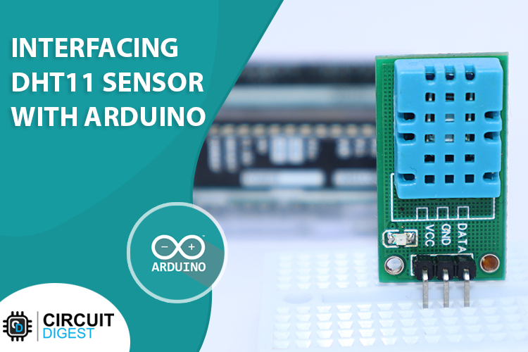
DHT11 Module features a temperature & humidity sensor complex with a calibrated digital signal output. The exclusive digital-signal-acquisition technique and temperature & humidity sensing technology ensure high reliability and excellent long-term stability. This sensor includes an NTC for temperature measurement and a resistive-type humidity measurement component for humidity measurement. These are connected to a high-performance 8-bit microcontroller, offering excellent quality, fast response, anti-interference ability, and cost-effectiveness.
DHT11 Module Pinout
The DHT11 module has a total of 3 pins. In which two are for power and one is for communication. The pinout of a DHT11 Sensor module is as follows:
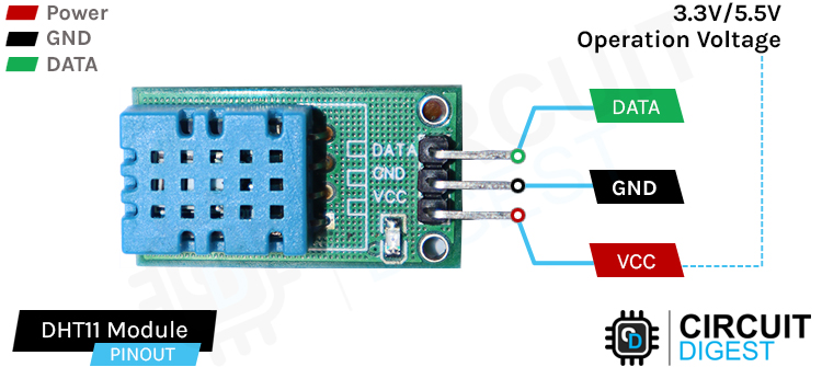
DATA Data pin for 1-wire communication.
GND Ground Connected to Ground pin of the Arduino.
VCC Provides power for the module, Connect to the 5V pin of the Arduino.
DHT11 Module Parts
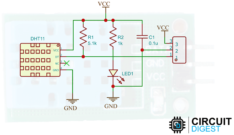
The DHT11 module has only a very low number of parts that includes the DHT11, pullup resistor, bypass capacitor, and power led with a current limiting resistor.

DHT11 Module Circuit Diagram
The schematic diagram for the DHT11 module is given below. As mentioned earlier, the board has a very low components count. The VCC and GND are directly connected to the DHT11 and a pullup resistor is added to the DATA pin. Sufficient filtering is provided with the tantalum and multilayer capacitors. An LED with a current limit resistor is used as a power indicator.
Commonly Asked Questions about DHT11 Sensor
Q. What does a DHT11 do?
The DHT11 is a basic, ultra-low-cost digital temperature and humidity sensor. It uses a capacitive humidity sensor and a thermistor to measure the surrounding air and sends data through a 1-wire protocol.
Q. How accurate is DHT11?
DHT11 can measure temperature from 0-50⁰C with a 2% accuracy and relative humidity from 20-80% with an accuracy of 5%.
Q. Is the DHT11 waterproof?
No. It’s not waterproof.
Q. What’s the sampling rate of a DHT11 sensor?
DHT11 has a sampling rate of 1Hz.
How does DHT11 Work?
As already mentioned, DHT11 has an NTC thermistor and humidity sensing components. When the temperature changes, the resistance of the NTC also changes. This change in resistance is measured and the temperature is calculated from it. We have already discussed how to use the NTC thermistor with Arduino.
The humidity sensing component consists of a moisture-holding substrate sandwiched in between two electrodes. When the substrate absorbs water content, the resistance between the two electrodes decreases. The change in resistance between the two electrodes is proportional to the relative humidity. Higher relative humidity decreases the resistance between the electrodes, while lower relative humidity increases the resistance between the electrodes. This change in resistance is measured with the onboard MCU’s ADC and the relative humidity is calculated.
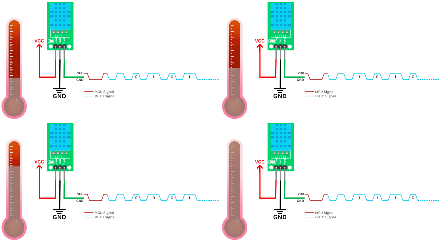
Each DHT11 element is strictly calibrated in the laboratory which is extremely accurate in humidity calibration. The calibration coefficients are stored as programmes in the OTP memory, which are used by the sensor’s internal signal detecting process.
DHT11 1-Wire Communication Protocol
Single-bus data format is used for communication and synchronization between MCU and DHT11 sensor. One communication process is about 4ms. Data consists of decimal and integral parts. Complete data transmission is 40bit, and the sensor sends higher data bit first. Data format is as follows: 8bit integral RH data + 8bit decimal RH data + 8bit integral T data + 8bit decimal T data + 8bit checksum. If the data transmission is right, the check-sum should be the last 8bit of "8bit integral RH data + 8bit decimal RH data + 8bit integral T data + 8bit decimal T data".
When MCU sends a start signal, DHT11 changes from the low-power-consumption mode to the running mode, waiting for MCU to complete the start signal. Once it is completed, DHT11 sends a response signal of 40-bit data that include the relative humidity and temperature information to the MCU. Users can choose to collect (read) some data. Without the start signal from MCU, DHT11 will not give the response signal to MCU. Once data is collected, DHT11 will change to the low power-consumption mode until it receives a start signal from MCU again.

The above image shows the communication timing diagram.
Circuit Diagram for Interfacing DHT11 Sensor with Arduino
Now that we have completely understood how a DHT11 Sensor works, we can connect all the required wires to Arduino and write the code to get all the data out from the sensor. The following image shows the circuit diagram for interfacing the DHT11 sensor module with Arduino.
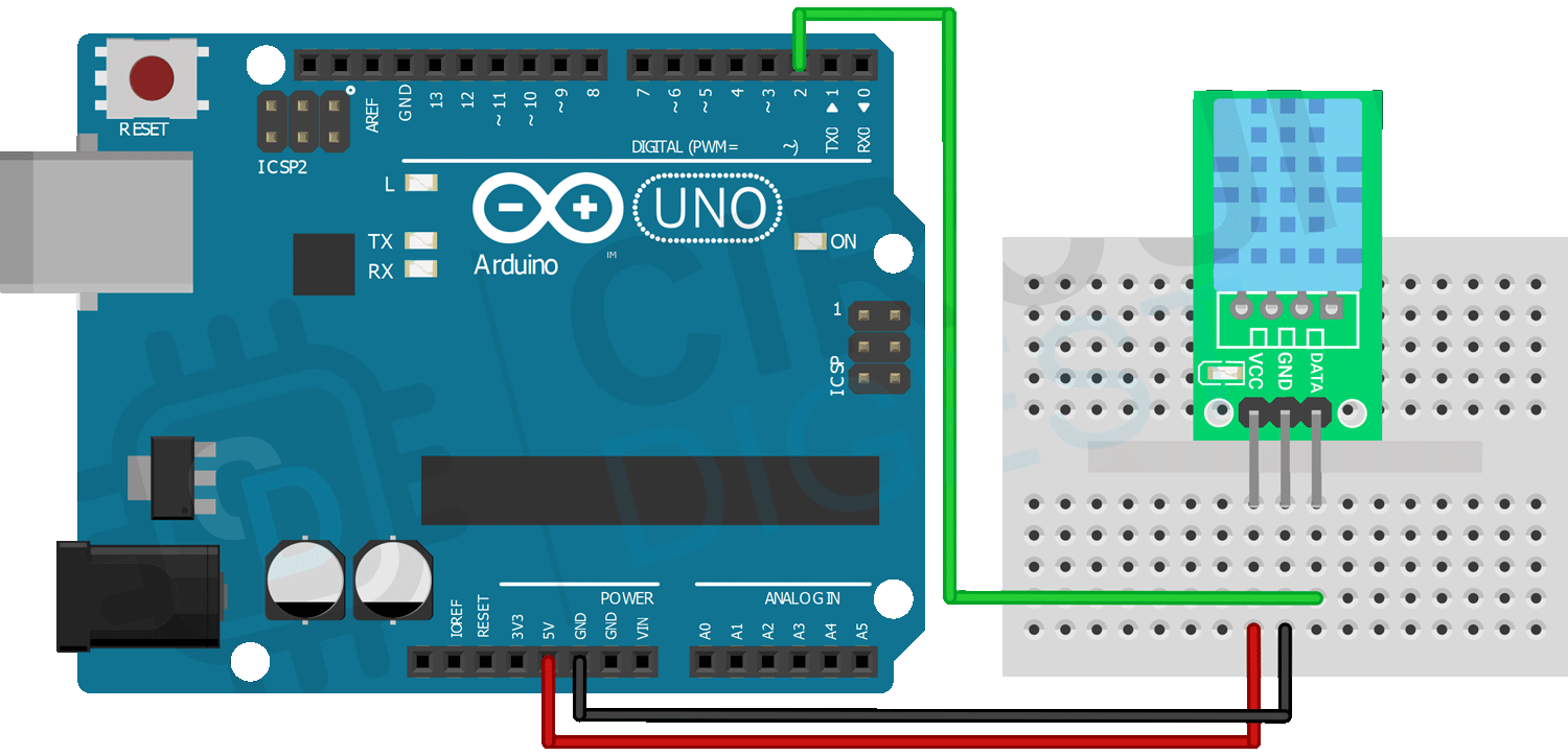
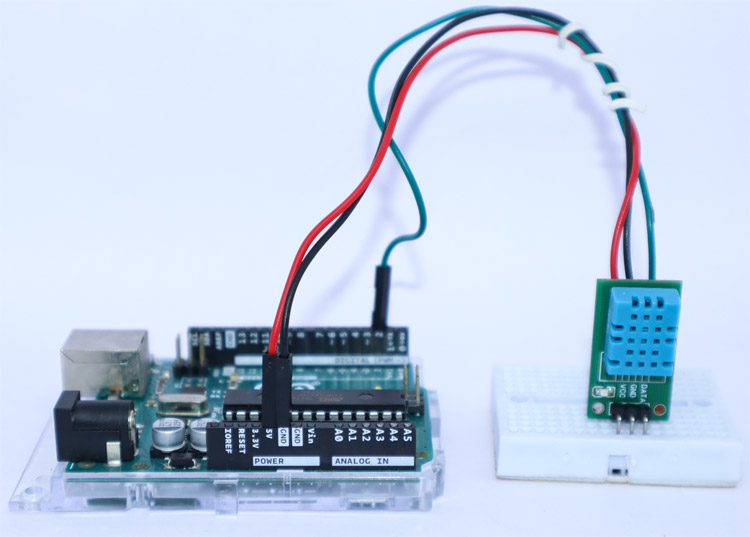
Connections are pretty simple and only require three wires. Connect the VCC and GND of the module to the 5V and GND pins of the Arduino. Then connect the DATA pin to the Arduino’s digital pin 2. We communicate with DHT11 through this pin.
Arduino DHT11 Code for Interfacing the Sensor Module
Now let’s look at the code for interfacing the DHT11 sensor. For that first install the Adafruit’s DHT sensor library and Adafruit Unified Sensor Driver through the library manager. Then create a blank sketch and paste the code at the end of this article into it.
#include <Adafruit_Sensor.h>
#include <DHT.h>
#include <DHT_U.h>
#define DHTTYPE    DHT11     // DHT 11
#define DHTPIN 2
DHT_Unified dht(DHTPIN, DHTTYPE);
uint32_t delayMS;
In the starting, we have included all the necessary libraries and defined the sensor type as DHT11 and the sensor pin as digital pin 2. And then created an instance for the DHT library. Also created a variable to declare the minimum delay.
 void setup() {
  Serial.begin(9600);
  dht.begin();
  sensor_t sensor;
  delayMS = sensor.min_delay / 1000;
}
In the setup function, we have initialized serial communication and the DHT library. Then the minimum delay for the data refresh.
void loop()
{
  sensors_event_t event;
  dht.temperature().getEvent(&event);
  Serial.print(F("Temperature: "));
  Serial.print(event.temperature);
  Serial.println(F("°C"));
  dht.humidity().getEvent(&event);
  Serial.print(F("Humidity: "));
  Serial.print(event.relative_humidity);
  Serial.println(F("%"));
  delay(delayMS);
}
In the loop function, we have created an event and using this event the temperature and humidity data is read from the DHT11 sensor. Then this value is printed to the serial monitor. The below GIF shows the DHT11 interface.
Projects using DHT11 Sensor
There are some interesting projects done with the DHT11 Sensor. If you want to know more about those topics, links are given below.
In this project, we will measure Humidity, Temperature and Pressure parameters and display them on the web server, which makes it a IoT based Weather Station where the weather conditions can be monitored from anywhere using the Internet.
In this project, we are going to make a small Automatic Temperature Control Circuit that could minimize the electricity charges by varying the AC temperature automatically based on the Room's temperature.
In this project, we are going to build a temperature-controlled fan using Arduino. With this circuit, we will be able to adjust the fan speed in our home or office according to the room temperature and also show the temperature and fan speed changes on a 16x2 LCD display.
Supporting Files
Complete Project Code
#include <Adafruit_Sensor.h>
#include <DHT.h>
#include <DHT_U.h>
#define DHTTYPE    DHT11     // DHT 11
#define DHTPIN 2
DHT_Unified dht(DHTPIN, DHTTYPE);
uint32_t delayMS;
void setup() {
  Serial.begin(9600);
  dht.begin();
  sensor_t sensor;
  delayMS = sensor.min_delay / 1000;
}

void loop()
{
  sensors_event_t event;
  dht.temperature().getEvent(&event);
  Serial.print(F("Temperature: "));
  Serial.print(event.temperature);
  Serial.println(F("°C"));
  dht.humidity().getEvent(&event);
  Serial.print(F("Humidity: "));
  Serial.print(event.relative_humidity);
  Serial.println(F("%"));
  delay(delayMS);
}


