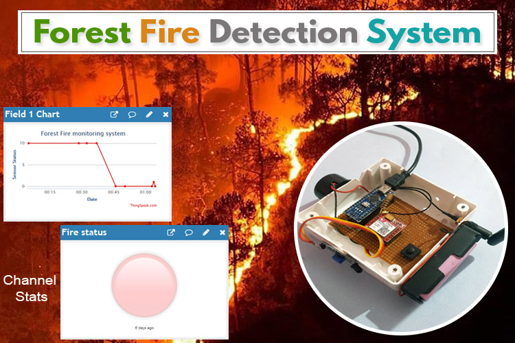
Forest fires are common hazards in forests that cause a lot of harm to Wildlife as well as the Environment. It could be avoided if a robust system could be deployed in forest areas to detect the fire and alert to Fire extinguishing authority to take immediate action. In this project, the intention is to build a Forest fire detection system using IoT which would detect the fire and send an emergency alert to Authority through IoT. Here a GSM/GPRS module is used to communicate with IoT sever as usually in forest areas network bandwidth is very low or not available. Hence a 2G network is preferable to communicate with the server.
Components Used
- Arduino Nano
- SIM800L GPS/GPRS Module
- 3.7V Li-ion Battery
- Flame sensor
- Dot matrix Perf board
SIM800L Module Working
SIM800L is a compact module that allows GPRS transmission, send/receive SMS, and making voice calls. SIM800L module has two antennas included on it. The first is for a ring antenna which can be soldered directly on the board and the other is meant for an external antenna.
Specification:
- Input voltage: 3.4V - 4.2V
- Interface: UART and AT commands
- Supported frequencies: Quad Band (850 / 950 / 1800 /1900 MHz)
- SIM card socket: micro SIM slot
- Antenna connector: IPX
- Working temperature range: -40 do + 85 ° C
Block Diagram for IoT Based Forest Fire Detection System
As shown in the schematic block diagram below, the project consists of Flame sensor, Arduino Nano & SIM800L GSM/GPRS module as its primary components. The fire can be detected by the flame sensor which gives a digital output that corresponds to the Fire status and is received by the Arduino Nano.
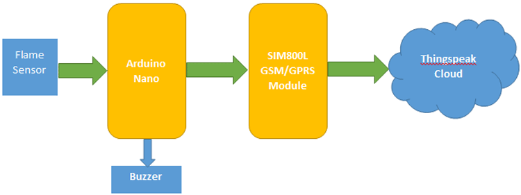
Arduino compares the signal and triggers the SIM800L in case of fire incidents. Through AT commands, SIM800L communicates with thingspeak server.
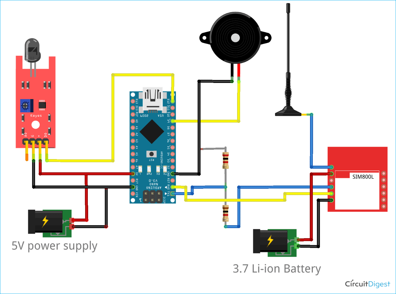
Arduino IoT Fire Detection - Circuit Diagram
As shown in the circuit diagram, the Flame sensor is connected to the Digital Input pin of Arduino Nano. You can also check out other simple fire alarm circuits which we have built earlier if you are interested.
SIM800L is connected to Arduino Nano via Logic shifting resistors as SIM800L works on 3.3v Logic. Separate power is given to SIM800L module because it works in 3.4-4.2V DC and 5V DC external supply is given to Arduino Nano. Alternatively, a 3.7-5 V Boost converter can be used here to avoid two power supplies.
Setup Thingspeak Account
After successful completion of hardware as per the above circuit diagram, the IoT platform needs to be set up, where the real-time data will be received. Here Thingspeak is used to store the parameters and show them in GUI. For creating an account in Thingspeak follow the steps below:
Step 1: Sign up for Thingspeak
First, go to https://thingspeak.com/ and create a new free Mathworks account if you don’t have a Mathworks account before.
Step 2: Sign in to Thingspeak
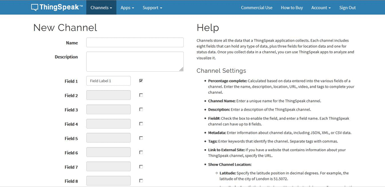
Sign in to Thingspeak using your credentials and click on “New Channel”. Now fill up the details of the project like Name, Field names, etc. Then click on “Save channel”.
Step 3: Record the Credentials
Select the created channel and record the following credentials.
- Channel ID, which is at the top of the channel view.
- Write API key, which can be found on the API Keys tab of your channel view.

Step 4: Add widgets to your GUI
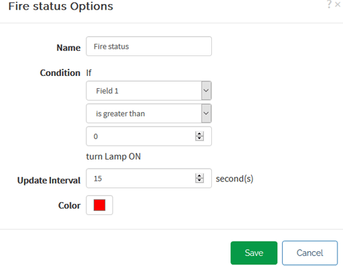
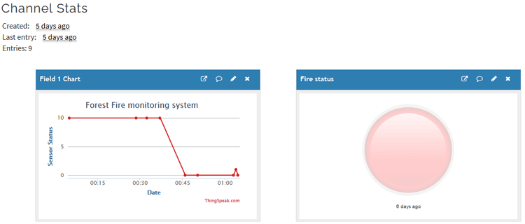
Click on “Add Widgets” and add four appropriate widgets like gauges, numeric displays, and indicators. In my case, I have taken Indicator for Fire Alert. Select appropriate field names for each widget.
Arduino Program for IoT Based Forest Fire Detection
After completion of successful hardware connection as per the circuit diagram, now it’s time to flash the code to Arduino. So the first step is to include all the required libraries in the code, which are “SoftwareSerial.h” and “String.h” in my case.
#include <SoftwareSerial.h>
#include <String.h>
The next step is to define the RX, TX Pin of Arduino where SIM800L is connected.
SoftwareSerial gprsSerial(10, 11);
In the setup (), all the primary initializations are made such as Serial initializations, SIM800L module initializations, and GPIO pin declarations.
void setup()
{
  pinMode(12, OUTPUT);
  pinMode(9, INPUT);
  gprsSerial.begin(9600);               // the GPRS baud rate
  Serial.begin(9600);    // the GPRS baud rate
  Module_Init();
}
In the SIM800L module initialization function, several AT commands are called to initialize the Module and know the status of the module. The functionalities of individual AT commands can be found in AT command sheet of SIM800L. But the only concern here is in the statement “gprsSerial.println("AT+CSTT=\"www\"")” where the access point of operator is defined. Make sure that, correct Access point name is replaced with “www”.
void Module_Init()
{
  gprsSerial.println("AT");
  delay(1000);
  gprsSerial.println("AT+CPIN?");
  delay(1000);
  gprsSerial.println("AT+CREG?");
  delay(1000);
  gprsSerial.println("AT+CGATT?");
  delay(1000);
  gprsSerial.println("AT+CIPSHUT");
  delay(1000);
  gprsSerial.println("AT+CIPSTATUS");
  delay(2000);
  gprsSerial.println("AT+CIPMUX=0");
  delay(2000);
  ShowSerialData();
  gprsSerial.println("AT+CSTT=\"www\"");
  delay(1000);
  ShowSerialData();
  gprsSerial.println("AT+CIICR");
  delay(3000);
  ShowSerialData();
  gprsSerial.println("AT+CIFSR");
  delay(2000);
  ShowSerialData();
  gprsSerial.println("AT+CIPSPRT=0");
  delay(3000);
  ShowSerialData();
}
Inside loop(), digital values from pin 12 are read and stored in a variable.
int fire = digitalRead(12);
Then, when the fire is detected, an if-else loop is used to detect the trigger of the SIM800L for necessary action. As shown below, AT+CIPSTART is used to connect with Thingspeak server and start the connection. The AT+CIPSEND is used to send the data to the server. Here one important thing is to replace the “Thingspeak write API Key” with your actual key in the string which was recorded earlier.
gprsSerial.println("AT+CIPSTART=\"TCP\",\"api.thingspeak.com\",\"80\"");//start up the connection
delay(6000);
ShowSerialData();
gprsSerial.println("AT+CIPSEND");//begin send data to remote server
delay(4000);
ShowSerialData();
String str = "GET https://api.thingspeak.com/update?api_key=ER43PWXXXXXQF0I&field1=" + String(1);
Serial.println(str);
gprsSerial.println(str);//begin send data to remote server
After completion of data transmission, AT+CIPSHUT is used to close the connection.
gprsSerial.println("AT+CIPSHUT");//close the connection
delay(100);
Forest Fire Detection System – Testing
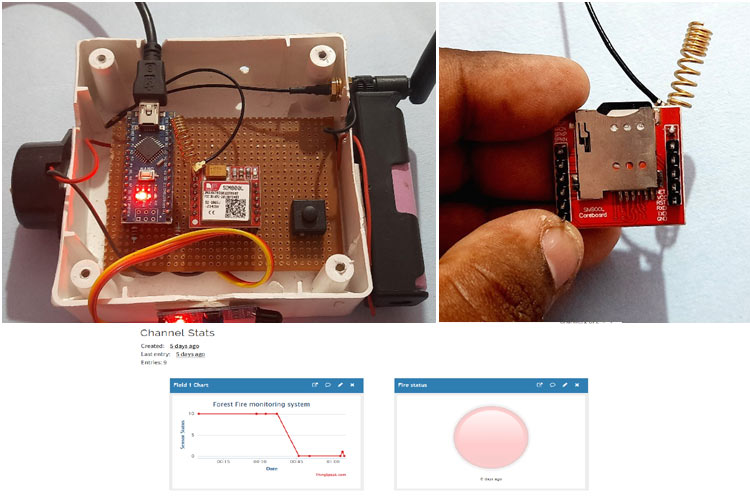
To test the prototype, first, the Microsim needs to be inserted in the SIM800L slot as shown in the figure. Then power ON the module and then we can see the LED blinking in the Module. If the LED blinking is delayed as compared to the initial start, it means it got the network, and is ready to connect to the server. Now we can see the status in Thingspeak server.
You can also check out the complete working of this project in the video linked below. Hope you enjoyed it and were able to build one on your own. If you have any questions, please leave them in the comments below or use our forums.
Complete Project Code
#include <SoftwareSerial.h>
SoftwareSerial gprsSerial(10, 11);
#include <String.h>
int flag = 0;
void setup()
{
  pinMode(9, OUTPUT);
  pinMode(12, INPUT);
  gprsSerial.begin(9600);               // the GPRS baud rate
  Serial.begin(9600);    // the GPRS baud rate
  Module_Init();
}
void loop()
{
  if (gprsSerial.available())
    Serial.write(gprsSerial.read());
  int fire = digitalRead(12);
  if (fire == 0)
  {
    digitalWrite(9, HIGH);
    gprsSerial.println("AT+CIPSTART=\"TCP\",\"api.thingspeak.com\",\"80\"");//start up the connection
    delay(6000);
    ShowSerialData();
    gprsSerial.println("AT+CIPSEND");//begin send data to remote server
    delay(4000);
    ShowSerialData();
    String str = "GET https://api.thingspeak.com/update?api_key=ER43PXXXXXHQF0I&field1=" + String(1);
    Serial.println(str);
    gprsSerial.println(str);//begin send data to remote server
    delay(4000);
    ShowSerialData();
    digitalWrite(9, LOW);
    gprsSerial.println((char)26);//sending
    delay(5000);//waitting for reply, important! the time is base on the condition of internet
    gprsSerial.println();
    ShowSerialData();
    gprsSerial.println("AT+CIPSHUT");//close the connection
    delay(100);
    ShowSerialData();
    flag = 0;
  }
  else
  {
    digitalWrite(9, LOW);
    if (flag == 0)
    {
      flag = 1;
      gprsSerial.println("AT+CIPSTART=\"TCP\",\"api.thingspeak.com\",\"80\"");//start up the connection
      delay(6000);
      ShowSerialData();
      gprsSerial.println("AT+CIPSEND");//begin send data to remote server
      delay(4000);
      ShowSerialData();
      String str = "GET https://api.thingspeak.com/update?api_key=ER43PWT91CGHQF0I&field1=" + String(0);
      Serial.println(str);
      gprsSerial.println(str);//begin send data to remote server
      delay(4000);
      ShowSerialData();
      digitalWrite(9, LOW);
      gprsSerial.println((char)26);//sending
      delay(5000);//waitting for reply, important! the time is base on the condition of internet
      gprsSerial.println();
      ShowSerialData();
      gprsSerial.println("AT+CIPSHUT");//close the connection
      delay(100);
      ShowSerialData();
    }
  }
}
void ShowSerialData()
{
  while (gprsSerial.available() != 0)
    Serial.write(gprsSerial.read());
  delay(5000);
}
void Module_Init()
{
  gprsSerial.println("AT");
  delay(1000);
  gprsSerial.println("AT+CPIN?");
  delay(1000);
  gprsSerial.println("AT+CREG?");
  delay(1000);
  gprsSerial.println("AT+CGATT?");
  delay(1000);
  gprsSerial.println("AT+CIPSHUT");
  delay(1000);
  gprsSerial.println("AT+CIPSTATUS");
  delay(2000);
  gprsSerial.println("AT+CIPMUX=0");
  delay(2000);
  ShowSerialData();
  gprsSerial.println("AT+CSTT=\"www\"");
  delay(1000);
  ShowSerialData();
  gprsSerial.println("AT+CIICR");
  delay(3000);
  ShowSerialData();
  gprsSerial.println("AT+CIFSR");
  delay(2000);
  ShowSerialData();
  gprsSerial.println("AT+CIPSPRT=0");
  delay(3000);
  ShowSerialData();
}

