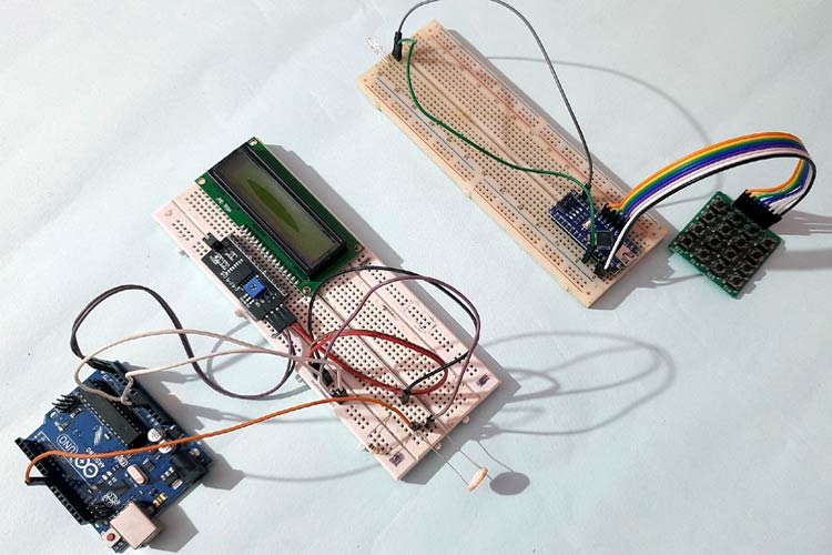
Li-Fi (Light Fidelity) is an advanced technology that allows transferring data using optical communication such as visible light. Li-Fi data can travel through the light and then interpreted on the receiver side using any light-sensitive device like LDR or photodiode. Li-Fi communication can be 100 times faster than Wi-Fi.
Here in this project, we will be demonstrating Li-Fi communication using two Arduino. Here the text data is transmitted using LED and 4x4 keypad. And it is decoded on the receiver side using LDR. We previously explained Li-Fi in detail and used Li-Fi to transfer audio signals.
Components Required
- Arduino UNO
- LDR Sensor
- 4*4 Keypad
- 16*2 Alphanumeric LCD
- I2C Interface module for LCD
- Breadboard
- Connecting Jumpers
- 5 mm LED
Brief Introduction to Li-Fi

As discussed above, Li-Fi is an advanced communication technology which can be 100 times faster than Wi-Fi communication. Using this technology, the data can be transferred using visible light sources. Imagine, if you can access to high-speed internet by just using your light source. Isn’t it seem very interesting?
Li-Fi uses visible light as a communication medium for the transmission of data. A LED can act as a light source and the photodiode acts as a transceiver that receives light signals and transmits them back. By Controlling the light pulse at the transmitter side, we can send unique data patterns. This phenomenon occurs at extremely high speed and can't be seen through the human eye. Then at the receiver side, the photodiode or Light-dependent resistor (LDR) converts the data into useful information.
Li-Fi Transmitter Section using Arduino
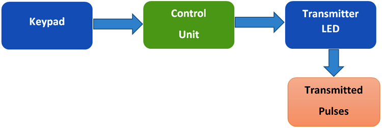
As shown in the figure above, in the transmitter part of Li-Fi communication, the keypad is used as input here. That means we’ll be selecting the text to be transmitted using the keypad. Then the information is processed by the control unit which is nothing but Arduino in our case. Arduino converts the information into binary pulses which can be fed to an LED source for transmission. Then these data are fed to LED light which sends the visible light pulses to the receiver side.
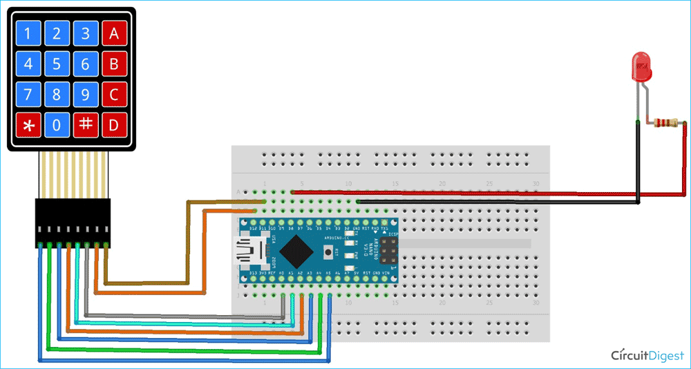
Circuit Diagram of Transmitter Section:
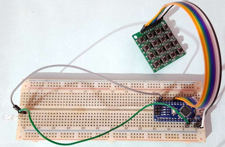
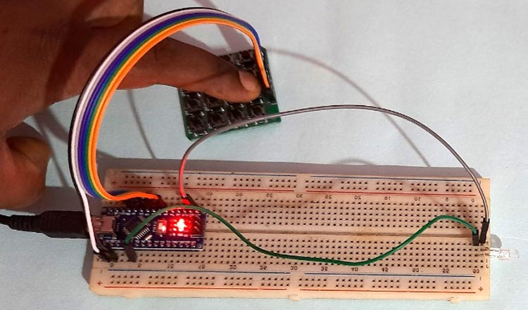
Hardware Setup for Transmitter Side:
Li-Fi Receiver Section using Arduino

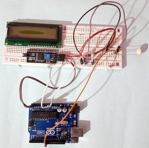
In the receiver section, the LDR sensor receives the visible light pulses from the transmitter side and converts it into interpretable electrical pulses, which is fed to the Arduino (Control unit). Arduino receives this pulse and converts it into actual data and displays it on a 16x2 LCD display.
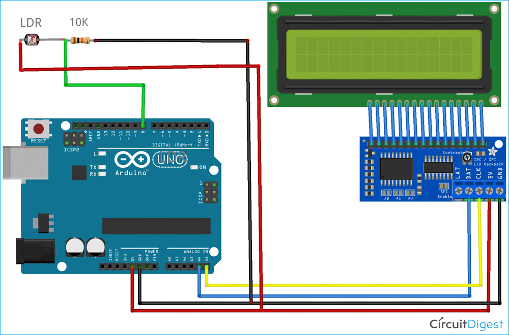
Circuit Diagram of Receiver Section:
Hardware Setup for Receiver Side:
Arduino Coding For Li-Fi
As shown above, we have two sections for Li-Fi Transmitter and Receiver. The complete codes for each section are given at the bottom of the tutorial and a stepwise explanation of codes are given below:
Arduino Li-Fi Transmitter Code:
In the Transmitter side, Arduino Nano is used with 4x4 Keypad and LED. First, all the dependent library files are downloaded and installed to Arduino via Arduino IDE. Here, the Keypad library is used for using 4*4 Keypad which can be downloaded from this link. Learn more about interfacing 4x4 keypad with Arduino here.
#include <Keypad.h>
After the successful installation of library files, define the no. of rows and column values which is 4 for both as we have used a 4*4 keypad here.
const byte ROW = 4;
const byte COL = 4;
char keyscode[ROW][COL] = {
  {'1', '2', '3', 'A'},
  {'4', '5', '6', 'B'},
  {'7', '8', '9', 'C'},
  {'*', '0', '#', 'D'}
};
Then, the Arduino pins are defined that are used to interface with the 4*4 keypad. In our case, we have used A5, A4, A3, and A2 for R1, R2, R3, R4 respectively, and A1, A0, 12, 11 for C1, C2, C3, and C4 respectively.
byte rowPin[ROW] = {A5, A4, A3, A2};
byte colPin[COL] = {A1, A0, 12, 11};
Keypad customKeypad = Keypad( makeKeymap(keyscode), rowPin, colPin, ROW, COL);
Inside setup (), the output pin is defined, where the LED source is connected. Also, it is kept OFF while switching ON the device.
void setup()
{
  pinMode(8,OUTPUT);
  digitalWrite(8,LOW);
}
Inside while loop, the values received from the keypad are read using customKeypad.getKey() and it is compared in the if-else loop, to generate unique pulses in each key presses. It can be seen in the code that the timer intervals are kept unique for all the key values.
char customKey = customKeypad.getKey();
  if (customKey) {
   if (customKey == '1')
  {
    digitalWrite(8,HIGH);
    delay(10);
    digitalWrite(8,LOW);
  }
Arduino Li-Fi Receiver Code:
In the Li-Fi receiver side, Arduino UNO is interfaced with an LDR sensor as shown in the circuit diagram. Here the LDR sensor is connected in series with a resistor to form a voltage divider circuit and the Analog voltage output from the sensor is fed to Arduino as an input signal. Here we are using an I2C module with LCD to reduce no. of connections with Arduino as this module requires only 2 data pins SCL/SDA and 2 power pins.
Start the code by including all the required library files in the code like Wire.h for I2C communication, LiquidCrystal_I2C.h for LCD, etc. These libraries would be pre-installed with Arduino, so there is no need to download them.
#include <Wire.h>
#include <LiquidCrystal_I2C.h>
For using the I2C module for 16*2 Alphanumeric LCD, configure it using the LiquidCrystal_I2C class. Here we have to pass the address, row, and column number which are 0x3f, 16, and 2 respectively in our case.
LiquidCrystal_I2C lcd(0x3f, 16, 2);
Inside setup (), declare the pulse input pin for receiving the signal. Then print a welcome message on the LCD which will be displayed during the initialization of the project.
void setup()
{
  pinMode(8, INPUT);
  Serial.begin(9600);
  lcd.init();
  lcd.backlight();
  lcd.setCursor(0, 0);
  lcd.print("       WELCOME TO              ");
  lcd.setCursor(0, 1);
  lcd.print("     CIRCUIT DIGEST              ");
  delay(2000);
  lcd.clear();
}
Inside the while loop, the pulse input duration from LDR is calculated using pulseIn function, and the type of pulse is defined which is LOW in our case. The value is printed on the serial monitor for debugging purposes. It is suggested to check the duration, as it might be different for different setups.
 unsigned long duration = pulseIn(8, HIGH);
 Serial.println(duration);
After checking the durations for all the transmitter pulses, we have now 16 pulse duration ranges, which is noted down for reference. Now compare them using an IF-ELSE loop for getting the exact data that has been transmitted. One sample loop for Key 1 is given below:
if (duration > 10000 && duration < 17000)
  {
    lcd.setCursor(0, 0);
    lcd.print("Received: 1          ");
  }
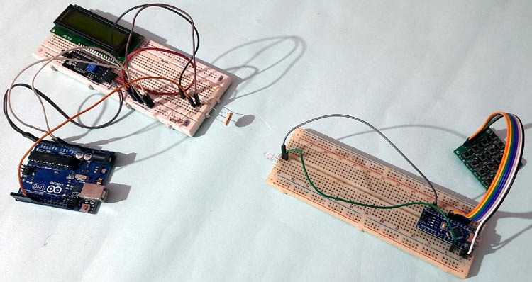
Li-Fi Transmitter and Receiver using Arduino
After uploading the complete code in both the Arduinos, press any button on the keypad at the receiver side and the same digit will be displayed on 16x2 LCD at the receiver side.
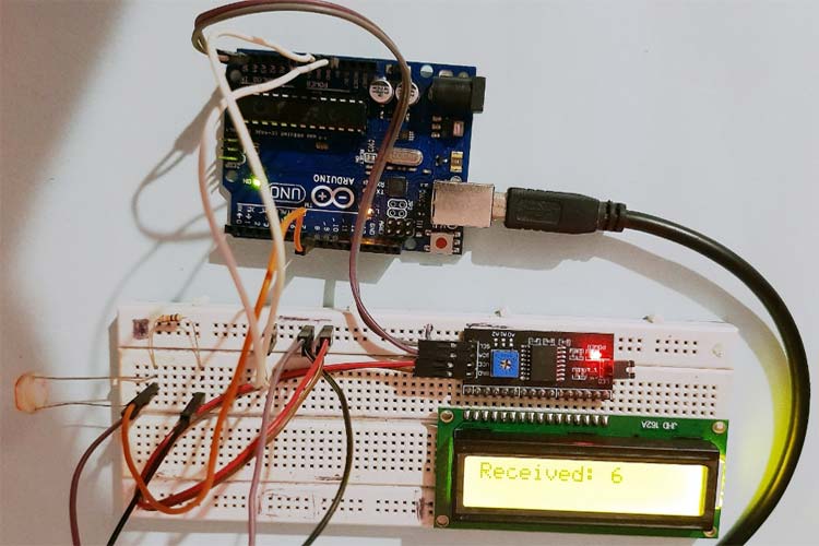
This is how Li-Fi can be used to transmit data through light. Hope you enjoyed the article and learned something new out of it, if you have any doubt, you can use the comment section or ask in forums.
Complete Project Code
//Transmitter Side:
#include <Keypad.h>
const byte ROW = 4;
const byte COL = 4;
char keyscode[ROW][COL] = {
  {'1', '2', '3', 'A'},
  {'4', '5', '6', 'B'},
  {'7', '8', '9', 'C'},
  {'*', '0', '#', 'D'}
};
byte rowPin[ROW] = {A5, A4, A3, A2};
byte colPin[COL] = {A1, A0, 12, 11};
Keypad customKeypad = Keypad( makeKeymap(keyscode), rowPin, colPin, ROW, COL);
char keycount = 0;
char code[5];
void setup()
{
  Serial.begin(9600);
  pinMode(8,OUTPUT);
  digitalWrite(8,LOW);
}
void loop()
{
  char customKey = customKeypad.getKey();
  if (customKey) {
    Serial.println(customKey);
   if (customKey == '1')
  {
    digitalWrite(8,HIGH);
    delay(10);
    digitalWrite(8,LOW);
  }
  else if (customKey == '2')
  {
    digitalWrite(8,HIGH);
    delay(20);
    digitalWrite(8,LOW);
  }
  else if (customKey == '3')
  {
    digitalWrite(8,HIGH);
    delay(30);
    digitalWrite(8,LOW);
  }
  else if (customKey == '4')
  {
    digitalWrite(8,HIGH);
    delay(40);
    digitalWrite(8,LOW);
  }
  else if (customKey == '5')
  {
    digitalWrite(8,HIGH);
    delay(50);
    digitalWrite(8,LOW);
  }
  else if (customKey == '6')
  {
    digitalWrite(8,HIGH);
    delay(60);
    digitalWrite(8,LOW);
  }
  else if (customKey == '7')
  {
    digitalWrite(8,HIGH);
    delay(70);
    digitalWrite(8,LOW);
  }
  else if (customKey == '8')
  {
    digitalWrite(8,HIGH);
    delay(80);
    digitalWrite(8,LOW);
  }
  else if (customKey == '9')
  {
    digitalWrite(8,HIGH);
    delay(90);
    digitalWrite(8,LOW);
  }
  else if (customKey == '*')
  {
    digitalWrite(8,HIGH);
    delay(100);
    digitalWrite(8,LOW);
  }
  else if (customKey == '0')
  {
    digitalWrite(8,HIGH);
    delay(110);
    digitalWrite(8,LOW);
  }
  else if (customKey == '#')
  {
    digitalWrite(8,HIGH);
    delay(120);
    digitalWrite(8,LOW);
  }
  else if (customKey == 'A')
  {
    digitalWrite(8,HIGH);
    delay(130);
    digitalWrite(8,LOW);
  }
  else if (customKey == 'B')
  {
    digitalWrite(8,HIGH);
    delay(140);
    digitalWrite(8,LOW);
  }
  else if (customKey == 'C')
  {
    digitalWrite(8,HIGH);
    delay(150);
    digitalWrite(8,LOW);
  }
  else if (customKey == 'D')
  {
    digitalWrite(8,HIGH);
    delay(160);
    digitalWrite(8,LOW);
  }
  else;
  }
}
//Receiver Side:
#include <Wire.h>
#include <LiquidCrystal_I2C.h>
LiquidCrystal_I2C lcd(0x27, 16, 2);
#include <SoftwareSerial.h>
#include <Keypad.h>
void setup()
{
  pinMode(8, INPUT);
  Serial.begin(9600);
  lcd.init();
  lcd.backlight();
  //lcd.backlight();
  lcd.setCursor(0, 0);
  lcd.print("   WELCOME TO    ");
  lcd.setCursor(0, 1);
  lcd.print(" CIRCUIT DIGEST    ");
  delay(2000);
  lcd.clear();
}
void loop()
{
  unsigned long duration = pulseIn(8, HIGH);
  Serial.println(duration);
  if (duration > 10000 && duration < 17000)
  {
    lcd.setCursor(0, 0);
    lcd.print("Received: 1          ");
  }
  else if (duration > 20000 && duration < 27000)
  {
    lcd.setCursor(0, 0);
    lcd.print("Received: 2          ");
  }
  else if (duration > 30000 && duration < 37000)
  {
    lcd.setCursor(0, 0);
    lcd.print("Received: 3          ");
  }
  else if (duration > 40000 && duration < 47000)
  {
    lcd.setCursor(0, 0);
    lcd.print("Received: 4          ");
  }
  else if (duration > 50000 && duration < 57000)
  {
    lcd.setCursor(0, 0);
    lcd.print("Received: 5          ");
  }
  else if (duration > 60000 && duration < 67000)
  {
    lcd.setCursor(0, 0);
    lcd.print("Received: 6          ");
  }
  else if (duration > 70000 && duration < 77000)
  {
    lcd.setCursor(0, 0);
    lcd.print("Received: 7          ");
  }
  else if (duration > 80000 && duration < 87000)
  {
    lcd.setCursor(0, 0);
    lcd.print("Received: 8          ");
  }
  else if (duration > 90000 && duration < 97000)
  {
    lcd.setCursor(0, 0);
    lcd.print("Received: 9          ");
  }
  else if (duration > 100000 && duration < 107000)
  {
    lcd.setCursor(0, 0);
    lcd.print("Received: *          ");
  }
  else if (duration > 110000 && duration < 117000)
  {
    lcd.setCursor(0, 0);
    lcd.print("Received: 0          ");
  }
  else if (duration > 120000 && duration < 127000)
  {
    lcd.setCursor(0, 0);
    lcd.print("Received: #          ");
  }
  else if (duration > 130000 && duration < 137000)
  {
    lcd.setCursor(0, 0);
    lcd.print("Received: A          ");
  }
  else if (duration > 140000 && duration < 147000)
  {
    lcd.setCursor(0, 0);
    lcd.print("Received: B          ");
  }
  else if (duration > 150000 && duration < 157000)
  {
    lcd.setCursor(0, 0);
    lcd.print("Received: C          ");
  }
  else if (duration > 160000 && duration < 167000)
  {
    lcd.setCursor(0, 0);
    lcd.print("Received: D          ");
  }
}
Comments
void loop()
void loop()
{
unsigned long duration = pulseIn(8, HIGH);
Serial.println(duration); AM NOT GETING OUTPUT HERE
Hey, thank you for sharing
Hey, thank you for sharing your knowledge. It helped me a lot for my own LiFi project
nothing is happening, not
nothing is happening, not getting any output can anyone explain please??
Not getting output. Only the…
Not getting output. Only the transmitter part is working. Can any one please help me



am not getting an output can someone debug it for me?