Security is a major concern in our day to day life, and digital locks have become an important part of these security systems. There are many types technologies available to secure our place, like PIR Based security systems, RFID based Security system, Laser security alarms, bio-matrix systems etc.
We have previously built Digital Lock with Password using Arduino and using 8051, here we are going to build this Digital Lock using Raspberry Pi with User Defined Password. Once the password is set, user can only access the door with correct password.
If you are not familiar with Raspberry Pi, we have created a series of tutorials to learn Raspberry Pi, with interfacing with all the basic components and some simple projects to start with, do check.
Components Used:
- Raspberry Pi (with booted SD card)
- Keypad Module
- Buzzer
- 16x2 LCD
- 10k pot
- 10k Resistor Pack (Pull-up)
- LED
- 1k Resistor
- Bread board
- CD/DVD trolley as Gate
- Power 5 volt
- Motor driver L293D
- 12 Volt Battery
- Connecting wires
Connecting 4x4 Keypad with Raspberry Pi using Multiplexing:
In this circuit, we have used Multiplexing Technique to interface the keypad for entering the password in the system. Here we are using 4x4 multiplex keypad with 16 keys. Normally if we want to use 16 keys then we need 16 pins for connection to Arduino but in multiplexing technique we need only 8 pins for interfacing 16 keys. So that it is a smart way to interface a keypad module. Learn more about Multiplexing technique and its working in this Digital Lock using 8051.
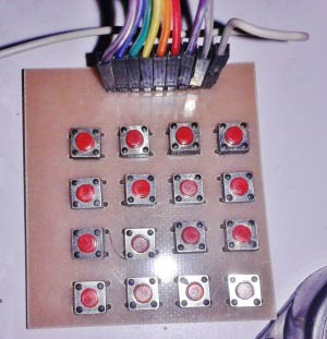
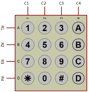
Multiplexing technique is a very efficient way to reduce the number of pins used with microcontroller for providing input or password or numbers. Basically this technique is used in two ways - one is row scanning and other one is column scanning. If we use keypad library (#include <Keypad.h>), like we did in this Digital Code Lock using Arduino, then we do not need to write any multiplexing code for this system. We only need to use keypad library for providing input.
But here in this project, we have implemented a short way of coding for the same keypad, without using the keypad library. Please see it in programming section below.
Circuit Description:
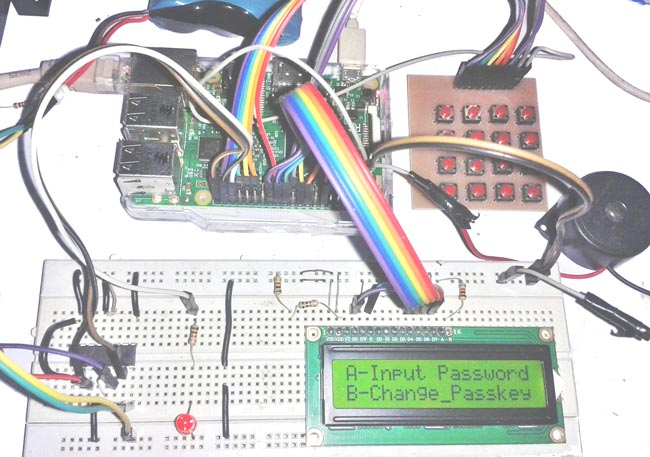
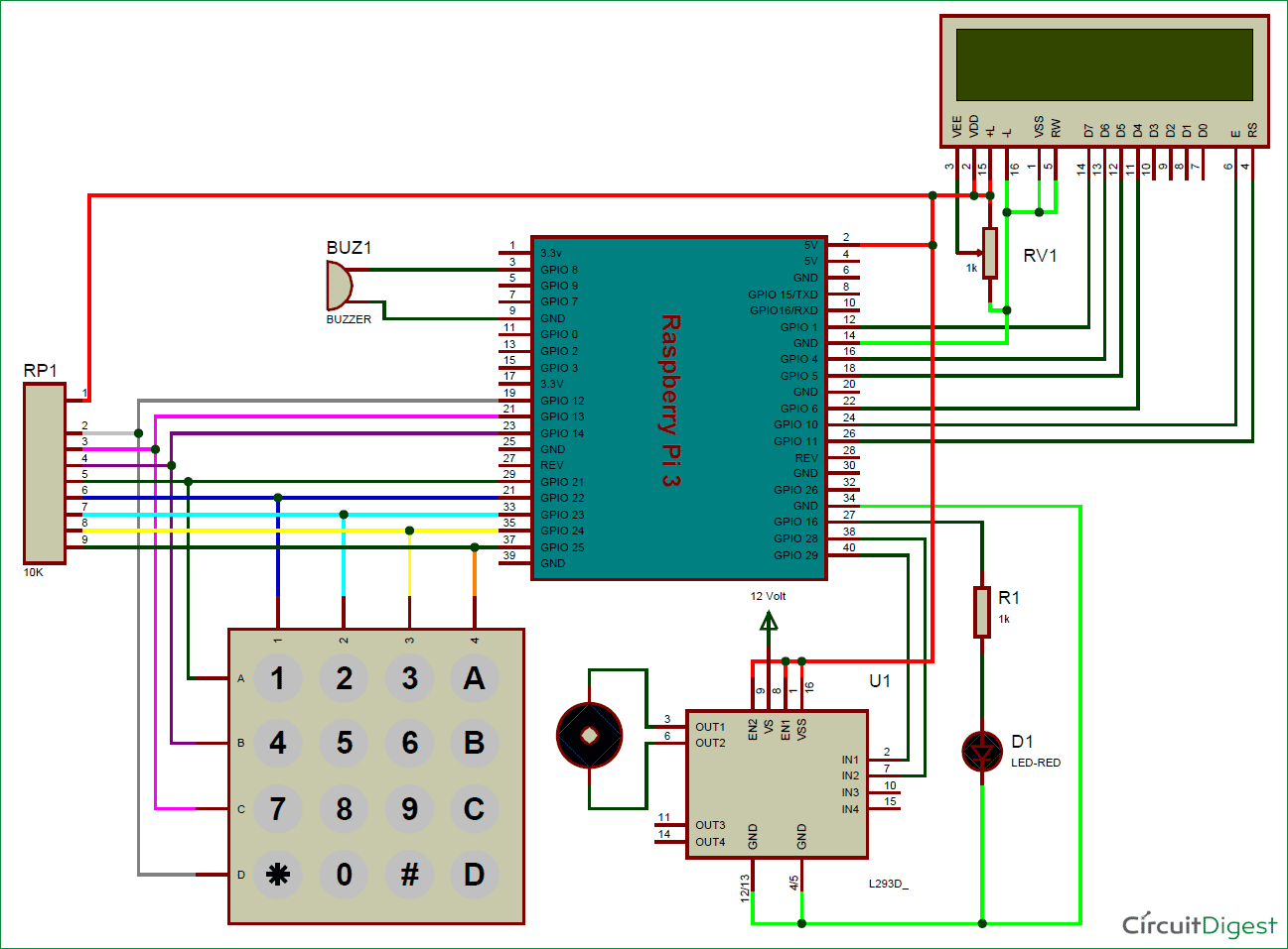
Circuit of this Raspberry Pi Digital Door Lock is very simple which contains Raspberry Pi 3, keypad module, buzzer, DVD/CD trolley as gate and LCD. Here Raspberry Pi controls the complete process like taking password form keypad module, comparing passwords, driving buzzer, opening/closing the gate and sending status to LCD display. Keypad is used for entering password. Buzzer is used for indications and driven by inbuilt NPN transistor. LCD is used for displaying status or messages on it.
Keypad module’s Column pins are directly connected to GPIO pin 22, 23, 24, 25 and Row pins are connected to 21, 14, 13, 12 of Raspberry Pi’s wringPi pins. A 16x2 LCD is connected with raspberry Pi in 4-bit mode. LCD’s control pin RS, RW and En are directly connected to GPIO pin 11, GND and 10. Data pins D4-D7 are connected to GPIO pins 6, 15, 4 and 1. One buzzer is connected at GPIO pin 8. And Motor Driver L293D is connected at GPIO pin 28 and 29 of Raspberry Pi. A 12 volt battery is connected at pin 8 of L293D with respect to ground.
Working Explanation:
Working of this project is simple. When user runs the code in Raspberry Pi, LCD shows some welcome message and after it show “A- Input Password” and in second line B- Change Passkey”. Now user can select their choice by pressing A and B at the keypad.
Now if user wants to open gate then he needs to press ‘A’ at the keypad and then system will ask for Password. Default Password is “1234”. Now user has to input the password and after this system will check the password, whether it is valid or not:
1. If user enters right password then system will open the gate.
2. If user enters wrong password the system will send command to buzzer to beep and shows “Access Denied” on the LCD.
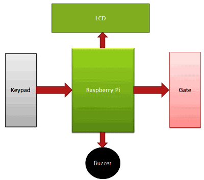
Now suppose user wants to change the password then he/she needs to press ‘B’ at the keypad and then user will be asked for “Current Password” or “Current Passkey”. Now user need to input the current password, then system check its correctness and perform one of the given tasks.
1. If user enters the right password then system will ask for “New Password” and now user can change the password by entering new password.
2. And if user enters the wrong password then system will drive the buzzer and shows “Wrong Password: on the LCD.
Now user needs to repeat whole process again to change password.
Basically, opening and closing the Gate is nothing but to rotate a Motor clock wise and anti-clockwise to open and close the door. For a small project you can simply add a DC motor to open and close the door. We can also use Servo or stepper motor, but we need to change the Code accordingly.
Further you can use a proper Electronic Door Lock (easily available online) in place of CD Trolley. It have an Electro magnet which keeps the Door locked when there is no current passed through the Lock (open circuit), and when some current passed through it, the lock gets unlocked and door can be opened. Code will be changed accordingly, also check this shared project review: Arduino RFID Door Lock
Programming Explanation:
Programming is much similar to Arduino. Arduino function uses classes but here we have done this code, using c programming, without classes. We have also installed a wiringPi library for GPIOs.
Now first of all we need to include required libraries and then define pins for LCD, buzzer, LED and Motor.
#include<wiringPi.h>
#include<string.h>
#include<stdio.h>

#define buzz 8
#define m1 29
#define m2 28
#define led 27

#define RS 11
#define EN 10
#define D4 6
#define D5 5
#define D6 4
#define D7 1
After it define pins for keypad’s row & columns and define array for storing password and keypad numbers.
char pass[4];
char pass1[]={'1','2','3','4'};
int n=0;
char row[4]={21, 14, 13, 12};
char col[4]={22, 23, 24, 25};

char num[4][4]={
                  {'1','2','3','A'},
                  {'4','5','6','B'},
                  {'7','8','9','C'},
                  {'*','0','#','D'}
                 };
After it we have written some functions for driving the LCD:
Function void lcdcmd is used for sending command to LCD and void write function is used for sending data to LCD.
Function void print is used for sending string to LCD.
void print(char *str)
 {
   while(*str)
   {
    write(*str);
    str++;
   }
 }
Function void setCursor is used for setting cursor position in the LCD.
void setCursor(int x, int y)
 {
   int set=0;
   if(y==0)
   set=128+x;
   if(y==1)
   set=192+x;
   lcdcmd(set);
 }
Function void clear() is used to clear the LCD and void buzzer() is used to beep the buzzer.
Function void gate_open(),void gate_stop() and void gate_close() are used for driving the Gate (CD Trolley)
void gate_open()
 {
   digitalWrite(m1, LOW);
   digitalWrite(m2, HIGH);
   delay(2000);
 }

 void gate_stop()
 {
   digitalWrite(m1, LOW);
   digitalWrite(m2, LOW);
   delay(2000);
 }

void gate_close()
 {
   digitalWrite(m1, HIGH);
   digitalWrite(m2, LOW);
   delay(2000);
 }
Given Function is used to initialize LCD in 4-bit Mode.
void begin(int x, int y)
 {
   lcdcmd(0x02);
   lcdcmd(0x28);
   lcdcmd(0x06);
   lcdcmd(0x0e);
   lcdcmd(0x01);
 }
Given void keypad() function is used for interfacing keypad module with Raspberry Pi with a ‘short method’.
void keypad()
{
   int i,j;
   int x=0,k=0;
   delay(2000);
   while(k<4)
   {
    for(i=0;i<4;i++)
    {
      digitalWrite(col[i], LOW);
      for(j=0;j<4;j++)
      {
        if(digitalRead(row[j])==0)
        {
          setCursor(x,1);
          .... ......
          ..... ......
Check all the functions in the Full code below, code is easy and self-explanatory.
Complete Project Code
#include<wiringPi.h>
#include<string.h>
#include<stdio.h>
#define buzz 8
#define m1 29
#define m2 28
#define led 27
#define RS 11
#define EN 10
#define D4 6
#define D5 5
#define D6 4
#define D7 1
char pass[4];
char pass1[]={'1','2','3','4'};
int n=0;
char row[4]={21, 14, 13, 12};
char col[4]={22, 23, 24, 25};
char num[4][4]={
                  {'1','2','3','A'},
                  {'4','5','6','B'},
                  {'7','8','9','C'},
                  {'*','0','#','D'}
                 };
void keypad();
void buzzer();
void lcdcmd(unsigned int ch)
  {
    int temp=0x80;
    digitalWrite(D4, temp & ch<<3);
    digitalWrite(D5, temp & ch<<2);
    digitalWrite(D6, temp & ch<<1);
    digitalWrite(D7, temp & ch);
    digitalWrite(RS, LOW);
    digitalWrite(EN, HIGH);
    delay(10);
    digitalWrite(EN, LOW);
    digitalWrite(D4, temp & ch<<7);
    digitalWrite(D5, temp & ch<<6);
    digitalWrite(D6, temp & ch<<5);
    digitalWrite(D7, temp & ch<<4);
    digitalWrite(RS, LOW);
    digitalWrite(EN, HIGH);
    delay(10);
    digitalWrite(EN, LOW);
  }
void write(unsigned int ch)
  {
    int temp=0x80;
    digitalWrite(D4, temp & ch<<3);
    digitalWrite(D5, temp & ch<<2);
    digitalWrite(D6, temp & ch<<1);
    digitalWrite(D7, temp & ch);
    digitalWrite(RS, HIGH);
    digitalWrite(EN, HIGH);
    delay(10);
    digitalWrite(EN, LOW);
    digitalWrite(D4, temp & ch<<7);
    digitalWrite(D5, temp & ch<<6);
    digitalWrite(D6, temp & ch<<5);
    digitalWrite(D7, temp & ch<<4);
    digitalWrite(RS, HIGH);
    digitalWrite(EN, HIGH);
    delay(10);
    digitalWrite(EN, LOW);
  }
void clear()
  {
     lcdcmd(0x01);
  }
  void setCursor(int x, int y)
  {
    int set=0;
    if(y==0)
    set=128+x;
    if(y==1)
    set=192+x;
    lcdcmd(set);
  }
  void print(char *str)
  {
    while(*str)
    {
     write(*str);
     str++;
    }
  }
  void begin(int x, int y)
  {
    lcdcmd(0x02);
    lcdcmd(0x28);
    lcdcmd(0x06);
    lcdcmd(0x0e);
    lcdcmd(0x01);
  }
  void enter()
  {
    clear();
    print("Current Passkey:");
    setCursor(0,1);
    keypad();
    if(strncmp(pass,pass1,4)==0)
    {
       clear();
       print("Enter New Passkey");
       setCursor(0,1);
       keypad();
       for(n=0;n<4;n++)
       pass1[n]=pass[n];
       clear();
       print("Passkey Changed.");
       delay(3000);
       return;
    }
    else
    {
      clear();
      print("Wrong Passkey");
      setCursor(0,1);
      print("Try again later");
     digitalWrite(led, HIGH);
      buzzer();
      buzzer();
      buzzer();
      buzzer();
      delay(2000);
      digitalWrite(led, LOW);
      return;
    }
  }
  void gate_open()
  {
     digitalWrite(m1, LOW);
     digitalWrite(m2, HIGH);
     delay(2000);
  }
  void gate_stop()
  {
    digitalWrite(m1, LOW);
    digitalWrite(m2, LOW);
    delay(2000);
  }
   void gate_close()
  {
    digitalWrite(m1, HIGH);
    digitalWrite(m2, LOW);
    delay(2000);
  }
  void choice()
  {
    digitalWrite(col[0], LOW);
    digitalWrite(col[1],HIGH);
     if(digitalRead(row[3])==0)
     {
       buzzer();
       clear();
       print("Enter Passkey:");
       setCursor(0,1);
       keypad();
       if(strncmp(pass,pass1,4)==0)
       {
        clear();
        print("   Welcome");
        setCursor(0,1);
        print("Access Granted");
        gate_open();
        gate_stop();
        gate_close();
        gate_stop();
        return;
       }
       else
       {
          clear();
          print("Access Denied");
          setCursor(0,1);
          print("Try again later");
          digitalWrite(led, HIGH);
          digitalWrite(buzz, HIGH);
          delay(3000);
          digitalWrite(led, LOW);
          digitalWrite(buzz, LOW);
          return;
       }
     }
     digitalWrite(col[0], HIGH);
     digitalWrite(col[1], LOW);
     if(digitalRead(row[3])==0)
     {
      buzzer();
      enter();
     }
  }
  void setup()
  {
  if(wiringPiSetup()==-1)
  printf("Error");
  pinMode(RS, OUTPUT);
  pinMode(EN, OUTPUT);
  pinMode(D4, OUTPUT);
  pinMode(D5, OUTPUT);
  pinMode(D6, OUTPUT);
  pinMode(D7, OUTPUT);
  pinMode(m1, OUTPUT);
  pinMode(m2, OUTPUT);
  pinMode(led, OUTPUT);
  pinMode(buzz, OUTPUT);
  for(n=0;n<4;n++)
  pinMode(row[n], INPUT);
  for(n=0;n<4;n++)
  pinMode(col[n], OUTPUT);
  for(n=0;n<4;n++)
  digitalWrite(col[n], HIGH);
  }
void main(void)
{
    setup();
    begin(16,2);
    print("Electronic Door");
    setCursor(0,1);
    print("Lock Using RPI ");
    delay(2000);
    clear();
    print("Circuit Digest");
    setCursor(0,1);
    print("Raspberry Pi");
    delay(2000);
    clear();
    while (1)
    {
     setCursor(0,0);
     //keypad();
     print("A-Input Password");
     setCursor(0,1);
     print("B-Change Passkey");
     choice();
    }
}
void buzzer()
{
   digitalWrite(buzz, HIGH);
   delay(200);
   digitalWrite(buzz, LOW);
}
void keypad()
{
   int i,j;
   int x=0,k=0;
   delay(2000);
   while(k<4)
   {
    for(i=0;i<4;i++)
    {
      digitalWrite(col[i], LOW);
      for(j=0;j<4;j++)
      {
        if(digitalRead(row[j])==0)
        {
          setCursor(x,1);
          write(num[i][j]);
          buzzer();
          setCursor(x,1);
          write('*');
          x++;
          pass[k++]=num[i][j];
          while(digitalRead(row[j])==0);
        }
      }
      digitalWrite(col[i], HIGH);
    }
  }
 }



Hi, can the pass words be changed every time someone new uses the device?
can you program it to do that?