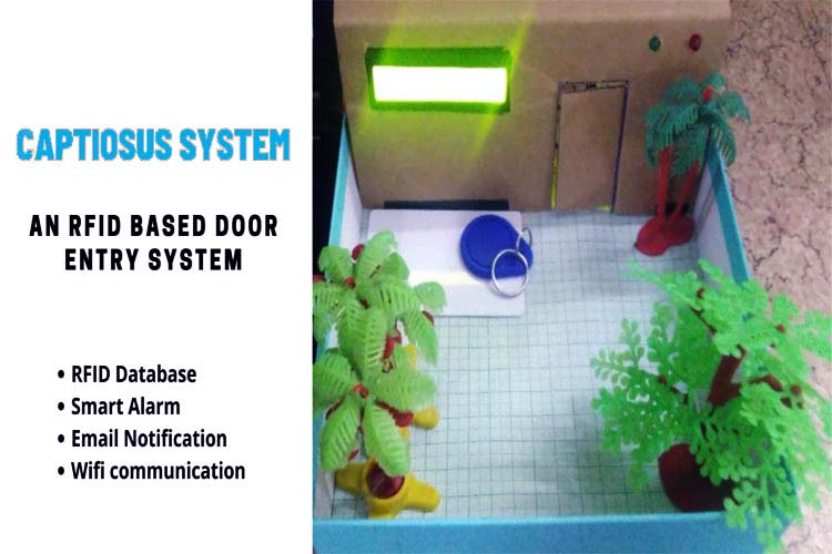
Every time I go out and lock my door using the traditional lock, I feel so outdated. I wanted to replace it with something interesting and modern, in terms of technology and uses. Something that can provide "better security" and "ease of use". So, I decided to build "An RFID Based Door Lock/Entry System." A system that can be used in every house or premises. It can normally be replaced with your traditional lock and has RFID tags as key to unlock the door. I named it "Captiosus System" (Captiosus is the Latin word, that means smart in English).
This system has an RFID scanner where you scan your RFID tag (Only registered RFID tags in the system database) and it opens the door. This system has an alarm system also for the person who is trying to enter with non-registered RFIDs. It has an email notification for all the entries (Permitted and denied entries). This system uses the best combination of hardware and software and can be considered as the best use of modern technology to modernize our way of living. You are connected to your security all the time and have a secure feel in your premises.
We already built some door security project,
- Digital Keypad Security Door Lock using Arduino
- Arduino Solenoid Door Lock using RFID
- Arduino RFID Door Lock
- ESP32-CAM Face Recognition Door Lock System
- RFID Door Lock System using Arduino
Component Required for RFID Based Door
Project Used Hardware
Raspberry Pi 3 B+,
RC522 RFID Scanner,
RFID Tags,
16*2 LCD Display,
Buzzer,
5 mm Green LED,
5 mm Red LED,
SG90 Servo Motor,
5V Power Supply,
Jumper Wires
Project Used Software
Thonny Python IDE,
VNC Viewer,
Project Hardware/Software Selection

Hardware and Software selection is based on various criteria, different components are selected for different reasons. Selection criteria are discussed below-
Raspberry Pi 3 B+
Raspberry Pi is selected as a central processing unit because of its multifunctionality and easy availability in the market. The possibility of scalability and further development of the project is considered during hardware selection and Raspberry Pi is a great fit for it.
RC522 RFID Module
RC522 RFID Module is easily available in the market in the has low power consumption, it can be easily implemented in any project. It is chosen for its various features including low power consumption, faster data transfer, portability, availability etc. It consists of an RFID scanner and RFID Tags.
16 * 2 LCD Display
To provide text assistance, the project needs a display, 16*2 LCD display is perfect for this because of its portability, low power consumption, cost etc.
Buzzer
To provide some sound outputs during the use of the system, a small buzzer is always fit. It has perfect sound and low power consumption.
LED Lights
Simple colorful LED lights are selected due to their brightness, compactness, and cost.
SG90 Servo Motor
This project has a small gate prototype that can be opened with any small low power servo motor. SG90 Servo Motor was easily available in the market and is very easy to use, so it is a great fit for the project.
Power Supply and Wires
As per other hardware requirements.
Thonny Python IDE
Thonny is an "open source" and pre-installed IDE in Raspberry Pi so it work great for the project.
VNC Viewer
To setup the Raspberry Pi as headless, VNC viewer has special version for Raspbian and is "open source" in nature. So VNC viewer is used for this project.
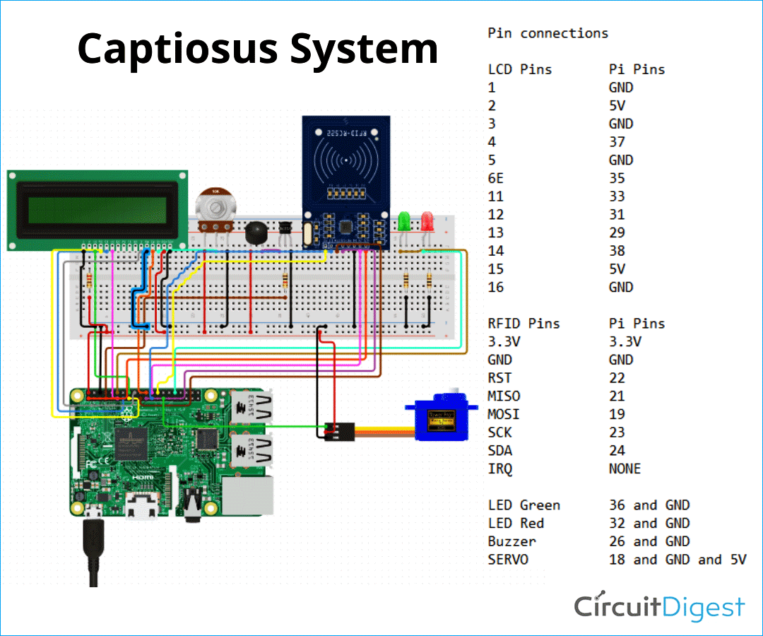
RFID Based Door Circuit Diagram
All the components are connected as per the given diagram. Some additional/ supportive components are connected with the main components also. Pin connections are done on basis of these given information.
LCD Pins Pi Pins 1 GND 2 5V 3 GND 4 37 5 GND 6 35 11 33 12 31 13 29 14 38 15 5V 16 GND
RFID Pins Pi Pins 3.3V 3.3V GND GND RST 22 MISO 21 MOSI 19 SCK 23 SDA 24 IRQ NONE
LED Green Pi pins Vcc 36 GND GND (A resistor is also added between Vcc of LED and Pin 36 of Raspberry Pi)
LED Red Pi pins Vcc 32 GND GND (A resistor is also added between Vcc of LED and Pin 32 of Raspberry Pi)
Buzzer Pi pins Vcc 26 GND GND
SERVO Pi pins Signal 18 GND GND Vcc 5V
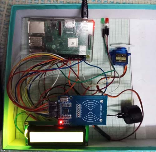
RFID Scanner, Buzzer, LEDs, Motor and Display is connected to Raspberry Pi as per given pin details - Raspberry Pi is connected to power supply - User scans his card and system calls the function based on the permission and denial of entry.
Complete Project Code
#Importing all the required libraries
import RPi.GPIO as GPIO
from RPLCD.gpio import CharLCD
import MFRC522
import signal
import time
from time import sleep
import smtplib
import os
#Setting up the SMTP
s = smtplib.SMTP('smtp.gmail.com', 587)
s.starttls()
s.login("captiosus.system@gmail.com", "Captiosus@123")
messagea = "Entry Detected- Permitted"
messageb = "Entry Detected- Denied"
subject = "Captiosus Alert"
message1 = 'Subject:{}\n{}'.format(subject, messagea)
message2 = 'Subject:{}\n{}'.format(subject, messageb)
#Setting up GPIO pins
GPIO.setmode(GPIO.BOARD)
GPIO.setup(11, GPIO.OUT)
pwm=GPIO.PWM(11, 50)
GPIO.setup(33, GPIO.OUT)
GPIO.setup(31, GPIO.OUT)
GPIO.setup(29, GPIO.OUT)
GPIO.setup(38, GPIO.OUT)
lcd = CharLCD(numbering_mode=GPIO.BOARD, cols=16, rows=2, pin_rs=37, pin_e=35, pins_data=[33, 31, 29, 38])
buzzer=26
led_n=32
led_r=36
GPIO.setup(buzzer,GPIO.OUT)
GPIO.setup(led_n,GPIO.OUT)
GPIO.setup(led_r,GPIO.OUT)
#Creating a function for Not Recognised Event
def notrecognised():
     GPIO.output(led_n,GPIO.HIGH)
     GPIO.output(buzzer,GPIO.HIGH)
     os.system("espeak-ng 'Your entry is denied'")
     lcd.cursor_pos = (0, 2)
     lcd.write_string('Entry Denied')
     sleep(0.3)
     GPIO.output(buzzer,GPIO.LOW)
     sleep(0.3)
     GPIO.output(buzzer,GPIO.HIGH)
     sleep(0.3)
     GPIO.output(buzzer,GPIO.LOW)
     sleep(0.3)
     GPIO.output(buzzer,GPIO.HIGH)
     sleep(0.3)
     GPIO.output(buzzer,GPIO.LOW)
     sleep(0.3)
     GPIO.output(buzzer,GPIO.HIGH)
     sleep(0.3)
     GPIO.output(buzzer,GPIO.LOW)
     sleep(0.3)
     GPIO.output(buzzer,GPIO.HIGH)
     sleep(0.3)
     GPIO.output(buzzer,GPIO.LOW)
     sleep(0.3)
     GPIO.output(buzzer,GPIO.HIGH)
     sleep(0.3)
     GPIO.output(buzzer,GPIO.LOW)
     GPIO.output(led_n,GPIO.LOW)
     lcd.clear()
#Creating a function for Recognised Event
def recognised():
     GPIO.output(led_r,GPIO.HIGH)
     GPIO.output(buzzer,GPIO.HIGH)
     os.system("espeak-ng 'You are welcome, please wear mask before you enter the room'")
     pwm.start(0)
     pwm.ChangeDutyCycle(10)
     lcd.cursor_pos = (0, 0)
     lcd.write_string('You are Welcome')
     sleep(0.5)
     GPIO.output(buzzer,GPIO.LOW)
     sleep(2.5)
     GPIO.output(led_r,GPIO.LOW)
     lcd.clear()
     pwm.ChangeDutyCycle(7.5) # neutral position
     sleep(1)
continue_reading = True
# Capture SIGINT for cleanup when the script is aborted
def end_read(signal,frame):
    global continue_reading
    print ("Ctrl+C captured, ending read.")
    continue_reading = False
    GPIO.cleanup()
# Hook the SIGINT
signal.signal(signal.SIGINT, end_read)
# Create an object of the class MFRC522
MIFAREReader = MFRC522.MFRC522()
# Welcome message
print ("Welcome to the MFRC522 data read example")
print ("Press Ctrl-C to stop.")
# This loop keeps checking for chips. If one is near it will get the UID and authenticate
while continue_reading:
    # Scan for cards
    (status,TagType) = MIFAREReader.MFRC522_Request(MIFAREReader.PICC_REQIDL)
    # If a card is found
    if status == MIFAREReader.MI_OK:
        print ("Card detected")
    # Get the UID of the card
    (status,uid) = MIFAREReader.MFRC522_Anticoll()
    # If we have the UID, continue
    if status == MIFAREReader.MI_OK:
        # Print UID
        print ("Card read UID: "+str(uid[0])+","+str(uid[1])+","+str(uid[2])+","+str(uid[3])+','+str(uid[4]))
        # This is the default key for authentication
        key = [0xFF,0xFF,0xFF,0xFF,0xFF,0xFF]
        # Select the scanned tag
        MIFAREReader.MFRC522_SelectTag(uid)
        #ENTER Your Card UID here (Registered database of RFIDs)
        my_uid = [178,2,40,49,169]
        #Check to see if card UID read matches your card UID
        if uid == my_uid:                #Open the Doggy Door if matching UIDs
            print("Access Granted")
            recognised()
            s.sendmail("captiosus.system@gmail.com", "garvitindian@gmail.com", message1)
        s.sendmail("captiosus.system@gmail.com", "shrutivij15@gmail.com",message1)
            time.sleep(1)
        else:                            #Don't open if UIDs don't match
            print("Access Denied, YOU SHALL NOT PASS!")
            notrecognised()
        s.sendmail("captiosus.system@gmail.com", "garvitindian@gmail.com",message2)
            s.sendmail("captiosus.system@gmail.com", "shrutivij15@gmail.com",message2)
        time.sleep(1)


