There are many ways to communicate between a product and a user, but the most common and popular choices for audio communication is the buzzer. The buzzer plays a very important role in electrical and electronic devices. We often encounter buzzers in common devices such as alarm clocks, doorbells, or other household appliances. However, many people are unaware of the various types of buzzers available and how they work. In this article, we will explore the internals of a buzzer, examine its internal structure, and gain a deeper understanding of its working system. Here, we will discuss difference between active buzzers and passive buzzers. The main function of this device is to convert an electrical signal to audio sound. Buzzers can be categorized into two different types active buzzers and passive buzzers, both of which are polarized.
Buzzer Pinout
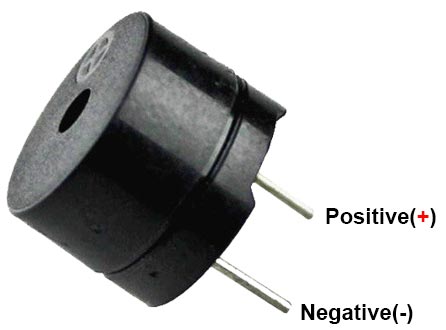
A buzzer has two pins, namely positive and negative. The positive terminal is represented by the ‘+’ symbol and negative terminal is represented by the ‘-’ symbol just like an led and a capacitor.
Difference between Active and Passive Buzzer
Active Buzzers: Active buzzers are called ‘active’ because they can produce sound directly when connected to a battery. If we connect the positive and negative terminals properly to the battery, It can generate sound by itself because it has a build-in oscillator. Active buzzers are the simplest to use. They are normally available in voltage ranges from 1.5V to 24V. they can produce a sound frequency of about 2kHz±300Hz. The current consumption of an active buzzer is ≤ 25mA.
Passive Buzzers: A passive buzzer can’t produce sound directly when connected to battery because it does not have an internal oscillating source. A passive buzzer requires an AC voltage signal source in order to make sound. It works like an electromagnetic squeaker, where changing input signal and frequency produces the sound. Therefore, these passive buzzers can produce a number of different tones based on the input frequency of the signal. The internal coil resistance of passive buzzer is very low, 16 ohm so it can draw a higher amount of current around 36mA. For safety, we can also connect 100ohm series resistor.
Working of Active & Passive Buzzers
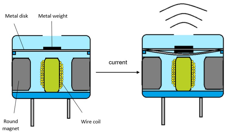
The basic idea of producing sound is through vibrations, as seen in human vocal cords the sound outcome is defined by the vibrations. Active and passive buzzers are types of magnetic buzzers. Inside the buzzer, there is a coil of wire that is connected to the buzzer’s pins. Additionally, there is a round magnet that surrounds the wire coil. A thin flexible ferromagnetic metal disk with a small metal weight attached to the top is positioned above the round magnet and wire coil. When pulses of current are applied to the wire coil, magnetic inductance causes the metal weight and metal disk to vibrate up and down. The vibration of the metal disk produces sound waves.
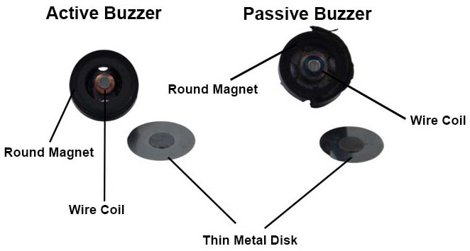
How to differentiate between Active & Passive buzzers?
As we can see in the picture below, the passive buzzer does not have a backside cover unlike the active buzzer. This can make it easier you to identify an active buzzer from a passive buzzer. However, it is not guaranteed to always look like this, and that’s why we need another test to ensure that what we think is an Active buzzer is actually correct.
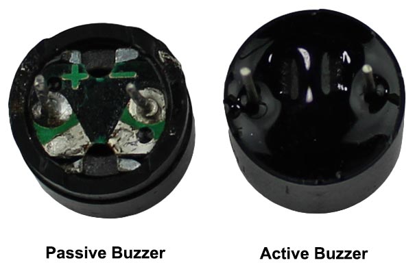
If buzzers cannot be identified just by looking at them, connect them to a +9V DC battery while keeping polarity in mind. This Because both types of buzzers have different responses to a constant +9V DC voltage.
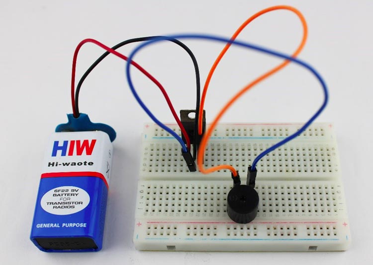
An active buzzer produces a continuous loud tone of buzzing sound until we disconnect the DC power supply, while a passive buzzer produces a pop and click sound similar to a relay when DC voltage is applied.
You can also use a multimeter to measure the resistance and identify whether it is an active or passive buzzer. First, set the multimeter in resistance mode and connect probes to the buzzer terminals. An active buzzer will show a lower resistance value, typically 16ohm. If the resistance value is high, then it is passive buzzer.
How to use a Active buzzer with Arduino?
Now that we know what active buzzer are, let’s go over how to connect one to your Arduino.
Components required
- An active buzzer
- Arduino board
- Breadboard
- Jumper wires
To begin, insert the active buzzer into the breadboard. Connect the positive pin (+) of the buzzer to the +5V VCC pin of the Arduino, and connect the negative pin (-) of the buzzer to the GND pin of the Arduino.
When the positive pin is connected to the 5V pin of Arduino directly, the buzzer produces a beep sound of constant frequency.
But this beep sound is uncontrolled continuous sound if we want to control the On and Off time duration of beep we need to write Arduino code.
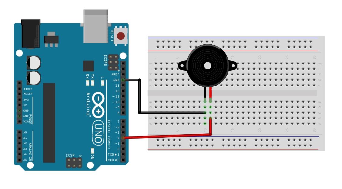
So now connect the positive pin(+) of buzzer to the Digital pin 4 of your Arduino(you can choice any digital pin) and negative pin(-) of buzzer to the GND pin of Arduino.
Now that we know how to set up our hardware, let’s move on to programming part.
Arduino code:
The code for this project is very simple. Connect the Arduino to your computer and open up the Arduino IDE.
Once the Arduino IDE is open, copy and past the following code into the editor.
Void setup() {
   pinMode(4,OUTPUT);
 }
 Void loop() {
  digitalWrite(4,HIGH);
  delay(2000);
  digitalWrite(4,LOW);
  delay(1000);
}
With this simple code, you can turn the active buzzer ON and OFF. We use delay to control how long the buzzer is on and off. The number inside the delay function is in milliseconds, which means that our buzzer turns on for 2 seconds and off for 1 second. You can also change it according to your needs.
How to use a Passive buzzer with Arduino?
The Passive Buzzer connection to the Arduino is exactly the same as what we’ve done with the Active Buzzer. We can use a PWM output pin to control the passive buzzer tone output. Or, alternatively, we can use any digital pin alongside the tone() and noTone() functions to control the passive buzzer.
Components required
- An passive buzzer
- Arduino board
- Breadboard
- Jumper wires
- 100ohm resistor
The tone of the passive buzzer can be controlled by adjusting the frequency applied to it. With Arduino, you can produce a square wave through its digital pins. By modifying the time duration for the high and low states of the square wave, you can change the frequency and, consequently, the tone of the passive buzzer.
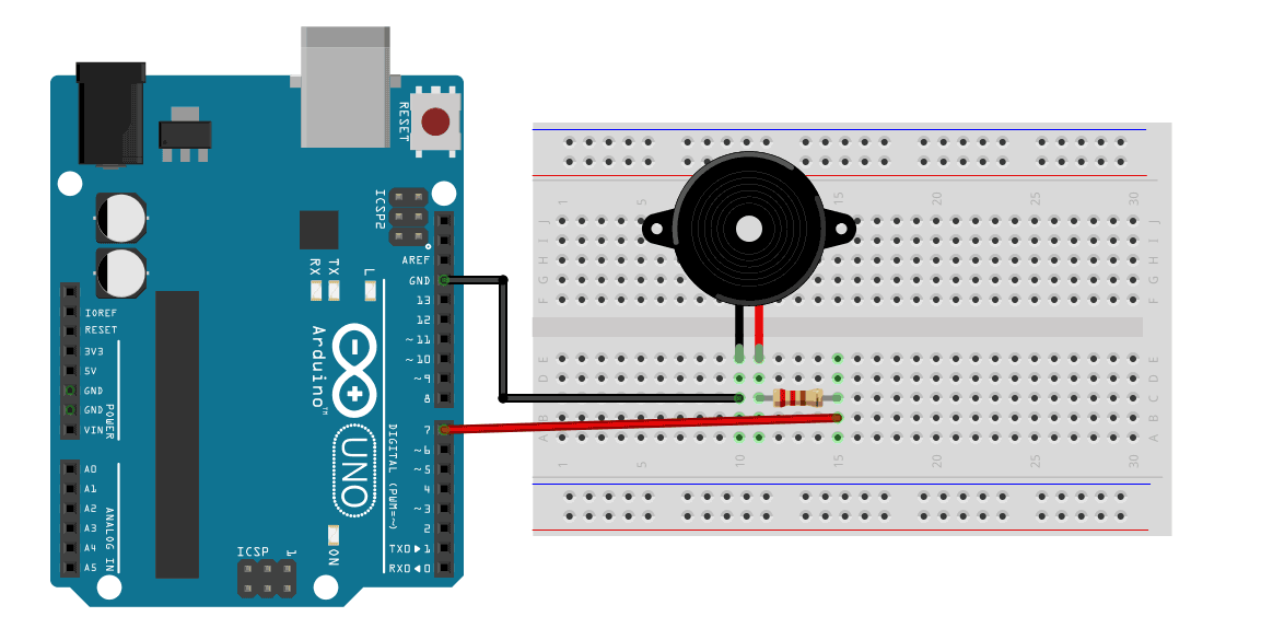
Make sure to connect positive pin(+) of buzzer to Arduino digital pin 7 and negative pin(-) to Arduino GND.
In same cases, you may want to connect 100ohm series resistor between buzzer positive(+) pin and Arduino digital pin.
Arduino code:
Arduino has a tone() function, which helps to generate the desirable frequency wave on digital pins.
In the similar way to keep buzzer silent over time we can use no tone() option.
tone() function have 3 following parameters.
tone(pin, frequency, duration);
- pin: Arduino pin on which to generate the tone.
- Frequency: the frequency of the tone in hertz.
- Duration: the duration of the tone in milliseconds.
Let’s build a code that cycles through a set of musical notes from sa, re, ga to ni.
int buzzerpin = 7;
void setup() {
 pinMode(buzzerpin,OUTPUT);
 tone(buzzerpin,500,2000);
}
void loop() {
 tone(buzzerpin,277);
 delay(1000);
 tone(buzzerpin,311);
 delay(1000)
 tone(buzzerpin,350);
 delay(1000);
 tone(buzzerpin,370);
 delay(1000);
 tone(buzzerpin,415);
 delay(1000);
 tone(buzzerpin,466);
 delay(1000);
 tone(buzzerpin,523);
 delay(1000);
 tone(buzzerpin,554);
 delay(1000);
 noTone(buzzerpin);
 delay(500);
  tone(buzzerpin,554);
 delay(1000);
 tone(buzzerpin,523);
 delay(1000);
 tone(buzzerpin,466);
 delay(1000);
 tone(buzzerpin,415);
 delay(1000);
 tone(buzzerpin,370);
 delay(1000);
 tone(buzzerpin,350);
 delay(1000);
 tone(buzzerpin,311);
 delay(1000);
 tone(buzzerpin,277);
 delay(1000);
 noTone(buzzerpin);
 delay(1000);}
The duration parameter doesn’t work very well when the tone() function is used in the loop() section. So to set the tone duration in the loop, use a delay() function after each tone() function. In this code, there is a delay() function that specifies a 1,000 millisecond (one second) delay after each tone() function.
At the end of the loop, the noTone() function and a delay of 1,000 milliseconds is used to add a one second period of silence before the loop repeats.
After you connect the buzzer and upload the code, you should hear the buzzer cycling through the 7 notes in a loop.
Applications
- Communication Devices
- Sound Effect
- Electronics used in Automobiles
- Tone-Generation
- Alarm Circuits
- Security Systems
- Timers
- Household Appliances
- Sporting Event
Complete Project Code
Active Buzzer Code
Void setup() {
   pinMode(4,OUTPUT);
}
Void loop() {
  digitalWrite(4,HIGH);
  delay(2000);
  digitalWrite(4,LOW);
  delay(1000);
}

Passive Buzzer Code
int buzzerpin = 7;
void setup() {
 pinMode(buzzerpin,OUTPUT);
 tone(buzzerpin,500,2000);
}
void loop() {
 tone(buzzerpin,277);
 delay(1000);
 tone(buzzerpin,311);
 delay(1000)
 tone(buzzerpin,350);
 delay(1000);
 tone(buzzerpin,370);
 delay(1000);
 tone(buzzerpin,415);
 delay(1000);
 tone(buzzerpin,466);
 delay(1000);
 tone(buzzerpin,523);
 delay(1000);
 tone(buzzerpin,554);
 delay(1000);
 noTone(buzzerpin);
 delay(500);
 tone(buzzerpin,554);
 delay(1000);
 tone(buzzerpin,523);
 delay(1000);
 tone(buzzerpin,466);
 delay(1000);
 tone(buzzerpin,415);
 delay(1000);
 tone(buzzerpin,370);
 delay(1000);
 tone(buzzerpin,350);
 delay(1000);
 tone(buzzerpin,311);
 delay(1000);
 tone(buzzerpin,277);
 delay(1000);
 noTone(buzzerpin);
 delay(1000);
}

