ADC is the Analog to Digital converter, which converts analog data into digital format; usually it is used to convert analog voltage into digital format. Analog signal has infinite no of values like a sine wave or our speech, ADC converts them into particular levels or states, which can be measured in numbers as a physical quantity. Instead of continuous conversion, ADC converts data periodically, which is usually known as sampling rate. Telephone modem is one of the examples of ADC, which is used for internet, it converts analog data into digital data, so that computer can understand, because computer can only understand Digital data. The major advantage, of using ADC is that, we noise can be efficiently eliminated from the original signal and digital signal can travel more efficiently than analog one. That’s the reason that digital audio is very clear, while listening.
In present time there are lots of microcontrollers in market which has inbuilt ADC with one or more channels. And by using their ADC register we can interface. When we select 8051 microcontroller family for making any project, in which we need of an ADC conversion, then we use external ADC. Some external ADC chips are 0803,0804,0808,0809 and there are many more. Today we are going to interface 8-channel ADC with AT89s52 Microcontroller namely ADC0808/0809.
Components:
- 8051 Microcontroller (AT89S52)
- ADC0808/0809
- 16x2 LCD
- Resistor (1k,10k)
- POT(10k x4)
- Capacitor(10uf,1000uf)
- Red led
- Bread board or PCB
- 7805
- 11.0592 MHz Crystal
- Power
- Connecting wires
ADC0808/0809:
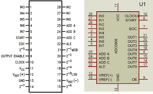
ADC0808/0809 is a monolithic CMOS device and microprocessor compatible control logic and has 28 pin which gives 8-bit value in output and 8- channel ADC input pins (IN0-IN7). Its resolution is 8 so it can encode the analog data into one of the 256 levels (28). This device has three channel address line namely: ADDA, ADDB and ADDC for selecting channel. Below is the Pin Diagram for ADC0808:

ADC0808/0809 requires a clock pulse for conversion. We can provide it by using oscillator or by using microcontroller. In this project we have applied frequency by using microcontroller.
We can select the any input channel by using the Address lines, like we can select the input line IN0 by keeping all three address lines (ADDA, ADDB and ADDC) Low. If we want to select input channel IN2 then we need to keep ADDA, ADDB low and ADDC high. For selecting all the other input channels, have a look on the given table:
|
ADC Channel Name |
ADDC PIN |
ADDB PIN |
ADDA PIN |
|
IN0 |
LOW |
LOW |
LOW |
|
IN1 |
LOW |
LOW |
HIGH |
|
IN2 |
LOW |
HIGH |
LOW |
|
IN3 |
LOW |
HIGH |
HIGH |
|
IN4 |
HIGH |
LOW |
LOW |
|
IN5 |
HIGH |
LOW |
HIGH |
|
IN6 |
HIGH |
HIGH |
LOW |
|
IN7 |
HIGH |
HIGH |
HIGH |
Circuit Description:
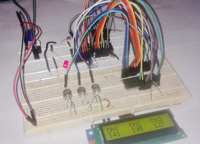
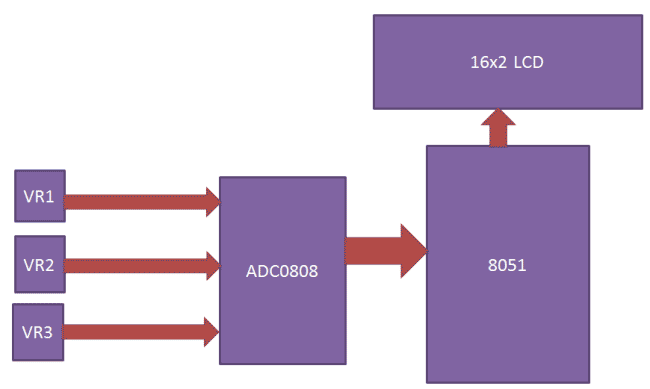
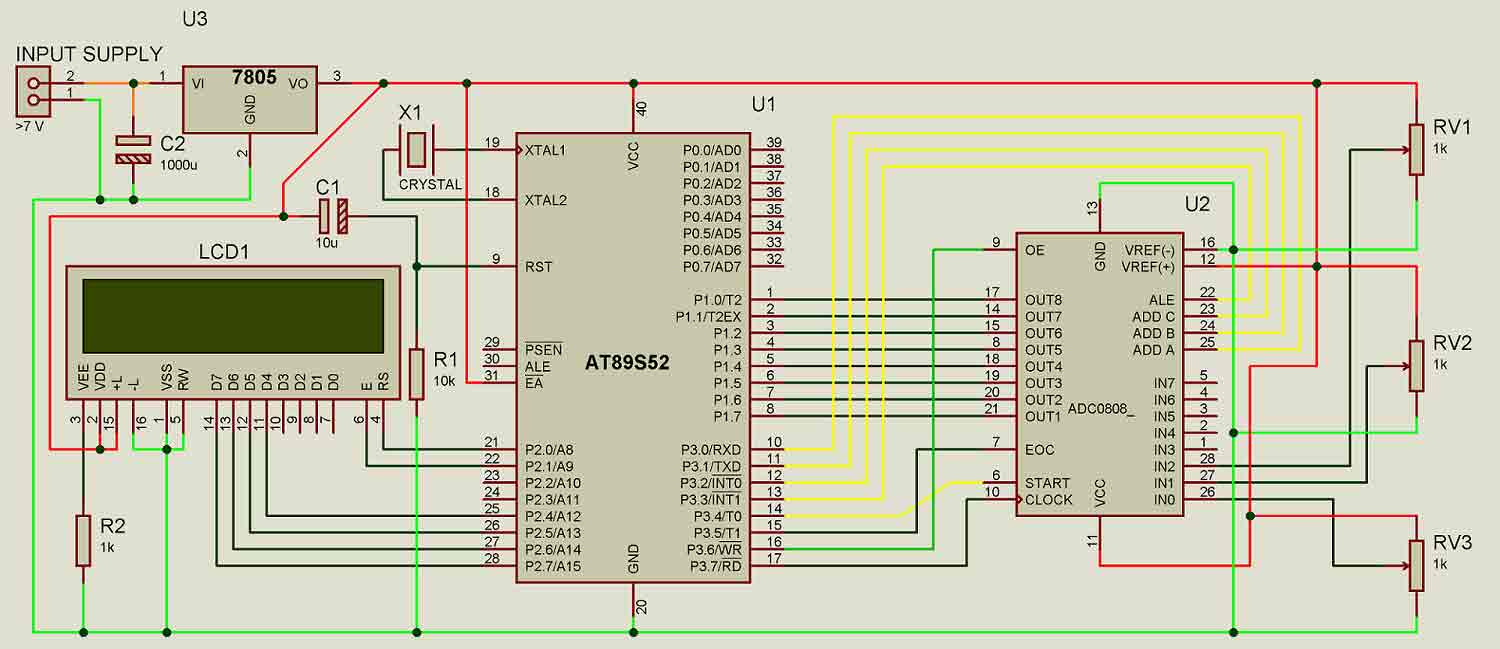
Circuit of “Interfacing ADC0808 with 8051” is little complex which contains more connecting wire for connecting device to each other. In this circuit we have mainly used AT89s52 as 8051 microcontroller, ADC0808, Potentiometer and LCD.
A 16x2 LCD is connected with 89s52 microcontroller in 4-bit mode. Control pin RS, RW and En are directly connected to pin P2.0, GND and P2.2. And data pin D4-D7 is connected to pins P2.4, P2.5, P2.6 and P2.7 of 89s52. ADC0808 output pin are directly connected to port P1 of AT89s52. Address line pins ADDA, ADDB, AADC are connected at P3.0, P3.1, and P3.2.
ALE (Address latch enable), SC (Start conversion), EOC (End of conversion), OE (Output enable) and clock pins are connected at P3.3, P3.4, P3.5, P3.6 and P3.7.
And here we have used three potentiometers connected at pin 26, 27, and 28 of ADC0808.
A 9 volt battery and a 5 volt voltage regulator namely 7805 are used for powering the circuit.
Working:
In this project we have interfaced three channels of ADC0808. And for demonstration we have used three variable resistors. When we power the circuit then microcontroller initialize the LCD by using appropriate command, gives clock to ADC chip, selects ADC channel by using address line and send start conversion signal to ADC. After this ADC first reads selected ADC channel input and gives its converted output to microcontroller. Then microcontroller shows its value at Ch1 position in LCD. And then microcontroller changes ADC channel by using address line. And then ADC reads selected channel and send output to microcontroller. And show on LCD as name Ch2. And like wise for other channels.

Working of ADC0808 is much similar to working of ADC0804. In this, first microcontroller provides a 500 KHz clock signal to ADC0808, using the Timer 0 interrupt, as ADC requires clock signal to operate. Now microcontroller sends a LOW to HIGH level signal to ALE pin (its active-high pin) of ADC0808 to enable the latch in the address. Then by applying HIGH to LOW Level signal to SC (Start Conversion), ADC starts analog to digital conversion. And then wait for the EOC (End of Conversion) pin to go LOW. When EOC goes LOW, it means analog to digital conversion has been completed and data is ready to use. After this, microcontroller enables the output line by applying a HIGH to LOW signal to OE pin of ADC0808.
ADC0808 gives ratio metric conversion output at its output pins. And the formula for radiometric conversion is given by:
Vin/(Vfs-Vz)= Dx/(Dmax-Dmin)
Where
Vin is input voltage for conversion
Vfs is full scale Voltage
Vz is zero voltage
Dx is data point being measure
Dmax is Maximum data limit
Dmin is Minimum data limit
Program Explanation:
In the program, first of all we include header file sand defines variable and input & output pins for ADC and LCD.
# include<reg51.h>
#include<stdio.h>
sbit ale=P3^3;
sbit oe=P3^6;
sbit sc=P3^4;
sbit eoc=P3^5;
sbit clk=P3^7;
sbit ADDA=P3^0;  //Address pins for selecting input channels.
sbit ADDB=P3^1;
sbit ADDC=P3^2;
#define lcdport P2  //lcd
sbit rs=P2^0;
sbit rw=P2^2;
sbit en=P2^1;
#define input_port P1  //ADC
int result[3],number;
Function for creating the delay has been created (void delay), along with some LCD functions like for LCD initialization, printing the string, for LCD commands etc. You can easily find them in Code. Check this article for LCD interfacing with 8051 and its functions.
After this in main program we have initialize LCD and set the EOC, ALE, EO, SC pins accordingly.
void main()
{
 int i=0;
 eoc=1;
 ale=0;
 oe=0;
 sc=0;
 TMOD=0x02;
 TH0=0xFD;
lcd_ini();
lcdprint(" ADC 0808/0809  ");
And then program reads the ADC and stores ADC output in a variable and then sends it to LCD after decimal to ASCII conversion, using void read_adc() and void adc(int i) functions:
void read_adc()
{
   number=0;
   ale=1;
   sc=1;
   delay(1);
   ale=0;
   sc=0;
   while(eoc==1);
   while(eoc==0);
   oe=1;
   number=input_port;
   delay(1);
   oe=0;
}

void adc(int i)
{
switch(i)
  {
   case 0:
    ADDC=0;
    ADDB=0;
    ADDA=0;
    lcdcmd(0xc0);
    read_adc();
Complete Project Code
# include<reg51.h>
#include<stdio.h>
sbit ale=P3^3;
sbit oe=P3^6;
sbit sc=P3^4;
sbit eoc=P3^5;
sbit clk=P3^7;
sbit ADDA=P3^0;  //Address pins for selecting input channels.
sbit ADDB=P3^1;
sbit ADDC=P3^2;
#define lcdport P2  //lcd
sbit rs=P2^0;
sbit rw=P2^2;
sbit en=P2^1;
#define input_port P1  //ADC
int result[3],number;
void timer0() interrupt 1  // Function to generate clock of frequency 500KHZ using Timer 0 interrupt.
{
clk=~clk;
}
void delay(unsigned int count)
{
int i,j;
for(i=0;i<count;i++)
  for(j=0;j<100;j++);
}
void daten()
{
    rs=1;
    rw=0;
    en=1;
    delay(1);
    en=0;
}
void lcd_data(unsigned char ch)
{
    lcdport=ch & 0xF0;
    daten();
    lcdport=ch<<4 & 0xF0;
    daten();
}
void cmden(void)
{
    rs=0;
    en=1;
    delay(1);
    en=0;
}
void lcdcmd(unsigned char ch)
{
    lcdport=ch & 0xf0;
    cmden();
    lcdport=ch<<4 & 0xF0;
    cmden();
}
lcdprint(unsigned char *str)  //Function to send string data to LCD.
{
    while(*str)
    {
        lcd_data(*str);
        str++;
    }
}
void lcd_ini()  //Function to inisialize the LCD
{
    lcdcmd(0x02);
    lcdcmd(0x28);
    lcdcmd(0x0e);
    lcdcmd(0x01);
}
void show()
{
   sprintf(result,"%d",number);
   lcdprint(result);
   lcdprint("  ");
}
void read_adc()
{
   number=0;
   ale=1;
   sc=1;
   delay(1);
   ale=0;
   sc=0;
   while(eoc==1);
   while(eoc==0);
   oe=1;
   number=input_port;
   delay(1);
   oe=0;
}
void adc(int i)  //Function to drive ADC
{
switch(i)
  {
   case 0:
    ADDC=0;  // Selecting input channel IN0 using address lines
    ADDB=0;
    ADDA=0;
    lcdcmd(0xc0);
    read_adc();
    show();
    break;
   case 1:
    ADDC=0;  // Selecting input channel IN1 using address lines
    ADDB=0;
    ADDA=1;
    lcdcmd(0xc6);
    read_adc();
    show();
   break;
   case 2:
    ADDC=0;  // Selecting input channel IN2 using address lines
    ADDB=1;
    ADDA=0;
    lcdcmd(0xcc);
    read_adc();
    show();
    break;
  }
}
void main()
{
 int i=0;
 eoc=1;
 ale=0;
 oe=0;
 sc=0;
 TMOD=0x02;
 TH0=0xFD;
lcd_ini();
lcdprint(" ADC 0808/0809  ");
lcdcmd(192);
lcdprint("  Interfacing   ");
delay(500);
lcdcmd(1);
lcdprint("Circuit Digest ");
lcdcmd(192);
lcdprint("System Ready...   ");
delay(500);
lcdcmd(1);
lcdprint("Ch1   Ch2   Ch3 ");
 IE=0x82;
 TR0=1;
while(1)
{
   for(i=0;i<3;i++)
   {
     adc(i);
     number=0;
   }
}
}
Comments
error solution
u have to change the : int result[3] into an (char result[3])character array because sprintf writes the data into an character array.
this code is not working i
this code is not working i guess due to the initialization its not working.it is showing some warning issues.
2 warnings like
adc single.c(84): warning C182: pointer to different objects
adc single.c(85): warning C182: pointer to different objects
code changes
I have made small changes to the original code.I have not tested on the actual hardware but i have done the simulation in proteus and it works.. Hope this helps
CODE:
#include<reg51.h>
#include<stdio.h>
sbit ale=P3^3;
sbit oe=P3^6;
sbit sc=P3^4;
sbit eoc=P3^5;
sbit clk=P3^7;
sbit ADDA=P3^0; //Address pins for selecting input channels.
sbit ADDB=P3^1;
sbit ADDC=P3^2;
#define lcdport P2 //lcd
sbit rs=P2^0;
sbit rw=P2^2;
sbit en=P2^1;
#define input_port P1 //ADC
char result[3];
int number;
void timer0() interrupt 1 // Function to generate clock of frequency 500KHZ using Timer 0 interrupt.
{
clk=~clk;
}
void delay(unsigned int count)
{
int i,j;
for(i=0;i<count;i++)
for(j=0;j<100;j++);
}
void daten()
{
rs=1;
rw=0;
en=1;
delay(1);
en=0;
}
void lcd_data(unsigned char ch)
{
lcdport=ch & 0xF0;
daten();
lcdport=ch<<4 & 0xF0;
daten();
}
void cmden(void)
{
rs=0;
en=1;
delay(1);
en=0;
}
void lcdcmd(unsigned char ch)
{
lcdport=ch & 0xf0;
cmden();
lcdport=ch<<4 & 0xF0;
cmden();
}
lcdprint(unsigned char *str) //Function to send string data to LCD.
{
while(*str)
{
lcd_data(*str);
str++;
}
}
void lcd_ini() //Function to inisialize the LCD
{
lcdcmd(0x02);
lcdcmd(0x28);
lcdcmd(0x0e);
lcdcmd(0x01);
}
void show()
{
sprintf(result,"%d",number);
lcdprint(result);
lcdprint(" ");
delay(50);
}
void read_adc()
{
number=0;
ale=1;
sc=1;
delay(1);
ale=0;
sc=0;
while(eoc==1);
while(eoc==0);
oe=1;
number=input_port;
delay(1);
oe=0;
}
void main()
{
int i=0;
eoc=1;
ale=0;
oe=0;
sc=0;
TMOD=0x02;
TH0=0xFD;
lcd_ini();
lcdprint(" ADC 0808/0809 ");
lcdcmd(192);
lcdprint(" Interfacing ");
delay(50);
lcdcmd(1);
lcdprint("Circuit Digest ");
lcdcmd(192);
lcdprint("System Ready... ");
delay(50);
lcdcmd(1);
lcdprint("Ch1 Ch2 Ch3 ");
IE=0x82;
TR0=1;
while(1)
{
for(i=0;i<3;i++)
{
number=0;
switch(i)
{
case 0:
ADDC=0; // Selecting input channel IN0 using address lines
ADDB=0;
ADDA=0;
lcdcmd(0xc0);
read_adc();
show();
break;
case 1:
ADDC=0; // Selecting input channel IN1 using address lines
ADDB=0;
ADDA=1;
lcdcmd(0xc6);
read_adc();
show();
break;
case 2:
ADDC=0; // Selecting input channel IN2 using address lines
ADDB=1;
ADDA=0;
lcdcmd(0xcc);
read_adc();
show();
break;
}
}
}
}
I GUESS HEX TO DECIMAL
I GUESS HEX TO DECIMAL CONVERSION SECTION IS MISSING IN THE CODE.....KINDLY CHECK....I HAVE NOT SEEN THIS SECTION IN ALL 8051 DISPLAY BASED PROJECT & EVERY BODY IS COMPLAINING CODE IS NOT WORKING....


Actually the code u have posted is not working i guess due to the initialization i think.I have changed some modifications too but still its not working.it is showing some warning issues.
CODE:
#include<reg51.h>
#include<stdio.h>
#define lcdport P2 //lcd
#define input_port P0 //ADC
sbit ale=P3^3;
sbit oe=P3^6;
sbit sc=P3^4;
sbit eoc=P3^5;
sbit clk=P3^7;
sbit ADDA=P3^0; //Address pins for selecting input channels.
sbit ADDB=P3^1;
sbit ADDC=P3^2;
sbit rs=P2^0;
sbit rw=P2^2;
sbit en=P2^1;
int result[3],number;
void timer0() interrupt 1 // Function to generate clock of frequency 500KHZ using Timer 0 interrupt.
{
clk=~clk;
}
void delay(unsigned int count)
{
int i,j;
for(i=0;i<count;i++)
for(j=0;j<1000;j++);
}
void daten()
{
rs=1;
rw=0;
en=1;
delay(1);
en=0;
}
void lcd_data(unsigned char ch)
{
lcdport=ch & 0xF0;
daten();
lcdport=ch<<4 & 0xF0;
daten();
}
void cmden(void)
{
rs=0;
en=1;
delay(1);
en=0;
}
void lcdcmd(unsigned char ch)
{
lcdport=ch & 0xf0;
cmden();
lcdport=ch<<4 & 0xF0;
cmden();
}
void lcdprint(unsigned char *str) //Function to send string data to LCD.
{
while(*str)
{
lcd_data(*str);
str++;
}
}
void lcd_init() //Function to prepare the LCD and get it ready
{
lcdcmd(0x38); // for using 2 lines and 5X7 matrix of LCD
delay(10);
lcdcmd(0x0F); // turn display ON, cursor blinking
delay(10);
lcdcmd(0x01); //clear screen
delay (10);
lcdcmd(0x80); // bring cursor to position 1 of line 1
delay (10);
}
/*
void lcd_ini() //Function to inisialize the LCD
{
lcdcmd(0x02);
lcdcmd(0x28);
lcdcmd(0x0e);
*/
void show()
{
sprintf(result,"%d",number);
lcdprint(result);
lcdprint(" ");
}
void read_adc()
{
number=0;
ale=1;
sc=1;
delay(1);
ale=0;
sc=0;
while(eoc==1);
while(eoc==0);
oe=1;
number=input_port;
delay(1);
oe=0;
}
void adc(int i) //Function to drive ADC
{
switch(i)
{
case 0:
ADDC=0; // Selecting input channel IN0 using address lines
ADDB=0;
ADDA=0;
lcdcmd(0xc0);
read_adc();
show();
break;
case 1:
ADDC=0; // Selecting input channel IN1 using address lines
ADDB=0;
ADDA=1;
lcdcmd(0xc6);
read_adc();
show();
break;
case 2:
ADDC=0; // Selecting input channel IN2 using address lines
ADDB=1;
ADDA=0;
lcdcmd(0xcc);
read_adc();
show();
break;
}
}
void main()
{
int i=0;
eoc=1;
ale=0;
oe=0;
sc=0;
TMOD=0x02;
TH0=0xFD;
lcd_init();
lcdprint(" ADC 0808/0809 ");
lcdcmd(192);
lcdprint(" Interfacing ");
delay(500);
lcdcmd(1);
lcdprint("Circuit Digest ");
lcdcmd(192);
lcdprint("System Ready... ");
delay(500);
lcdcmd(1);
lcdprint("Ch1 Ch2 Ch3 ");
IE=0x82;
TR0=1;
while(1)
{
for(i=0;i<3;i++)
{
adc(i);
number=0;
}
}
}
but i am getting 2 warnings like
adc single.c(84): warning C182: pointer to different objects
adc single.c(85): warning C182: pointer to different objects
i don't know why exactly the problem is.