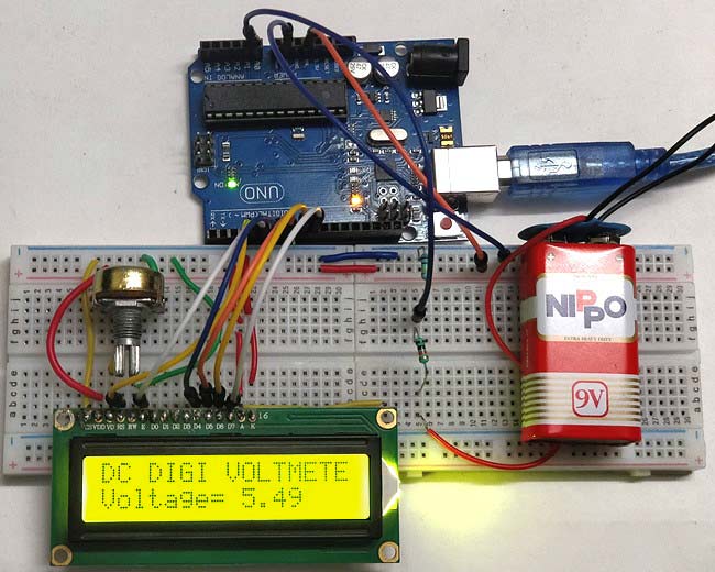
With a simple knowledge of Arduino and Voltage Divider Circuit, we can turn the Arduino into Digital Voltmeter and can measure the input voltage using Arduino and a 16x2 LCD display.
Arduino has several analog input pins that connect to an Analog-to-Digital converter (ADC) inside the Arduino. The Arduino ADC is a ten-bit converter, means that the output value will range from 0 to 1023. We will obtain this value by using the analogRead() function. If you know the reference voltage you can easily calculate the voltage present at the analog input. We can use voltage divider circuit to calculate the input voltage. Learn more about ADC in Arduino here.
The voltage measured is displayed on the 16x2 Liquid Crystal Display (LCD). We have also displayed the voltage in Serial Monitor of Arduino IDE and confirmed the measured voltage using Multimeter.
Hardware Required:
- Arduino uno
- 16x2 LCD (Liquid Crystal Display)
- 100 k ohm resistor
- 10 k ohm resistor
- 10 k ohm potentiometer
- breadboard
- jumper wires
Voltage Divider Circuit:
Before entering into this Arduino Voltmeter circuit, lets discuss about the Voltage Divider Circuit.
Voltage divider is a resistive circuit and is shown in figure. In this resistive network we have two resistors. As shown in figure, R1 and R2 which are of 10k and 100k ohm. The midpoint of branch is taken to measurement as a anolog input to the Arduino. The voltage drop across R2 is called Vout , that’s the divided voltage of our circuit.

Formulae:
Using the known value (two resistor values R1, R2, and the input voltage), we can substitute in the equation below to calculate the output voltage. You can also use our online voltage divider calculator to experiment with this formulae and try on your own.
Vout = Vin (R2/R1+R2)
This equation states that the output voltage is directly proportional to the input voltage and the ratio of R1 and R2.
By applying this equation in the Arduino code the input voltage can be easily derived. Arduino can only measure the DC input voltage of +55v, In other words, when measuring 55V, the Arduino analog pin will be at its maximum voltage of 5V so it is safe to measure within this limit. Here the resistors R2 and R1 value is set to 100000 and 10000 i.e. in the ratio of 100:10.
Circuit Diagram and Connections:
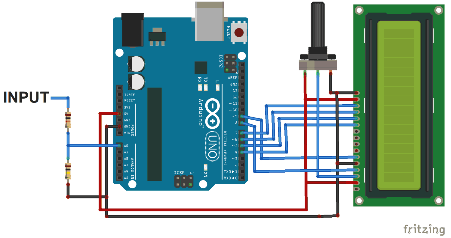
Connection for this Arduino Digital Voltmeter is simple and shown in the circuit diagram below:
Pin DB4, DB5, DB6, DB7, RS and EN of LCD are directly conneted to Pin D4, D5, D6, D7, D8, D9 of Arduino Uno
The Center point of two resistors R1 and R2, which makes the voltage divider circuit, is connected to Arduino Pin A0. While the other 2 ends are connected to the input volt (voltage to be measured) and gnd.
Coding Explanation:
Full Arduino code for measuring the DC voltage is given in the Code part below. Code is simple and can be easily understood.
The main part of the code is to convert and map the given input voltage into displayed output voltage with the help of the above given equation Vout = Vin (R2/R1+R2). As mentioned earlier Arduino ADC output value will range from 0 to 1023 and the Arduino max output voltage is 5v so we have to multiply the analog input at A0 to 5/1024 to get the real voltage.
void loop()
{
    int analogvalue = analogRead(A0);
    temp = (analogvalue * 5.0) / 1024.0;       // FORMULA USED TO CONVERT THE VOLTAGE
    input_volt = temp / (r2/(r1+r2));
Here we have displayed the measured voltage value on LCD and serial monitor of Arduino. So here in the code Serial.println is used to print the values on Serial monitor and lcd.print is used to print the values on 16x2 LCD.
    Serial.print("v= ");                 // prints the voltage value in the serial monitor
    Serial.println(input_volt);
    lcd.setCursor(0, 1);
    lcd.print("Voltage= ");               // prints the voltage value in the LCD display
    lcd.print(input_voltage);
This is how we can easily calculate the DC voltage using Arduino. Check the Video below for demonstration. Its bit difficult to calculate the AC voltage using Arduino, you can check the same here.
Complete Project Code
#include <LiquidCrystal.h>   // LIBRARY TO ACCESS THE LCD DISPLAY
LiquidCrystal lcd( 4, 5, 6, 7,8 ,9 );
float input_volt = 0.0;
float temp=0.0;
float r1=10000.0;    //r1 value
float r2=100000.0;      //r2 value
void setup()
{
   Serial.begin(9600);     //  opens serial port, sets data rate to 9600 bps
   lcd.begin(16, 2);       //// set up the LCD's number of columns and rows
   lcd.print("DC DIGI VOLTMETER");
}
void loop()
{
    int analogvalue = analogRead(A0);
    temp = (analogvalue * 5.0) / 1024.0;       // FORMULA USED TO CONVERT THE VOLTAGE
    input_volt = temp / (r2/(r1+r2));
if (input_volt < 0.1)
   {
     input_volt=0.0;
   }
    Serial.print("v= ");                 // prints the voltage value in the serial monitor
    Serial.println(input_volt);
    lcd.setCursor(0, 1);
    lcd.print("Voltage= ");               // prints the voltage value in the LCD display
    lcd.print(input_volt);
    delay(300);
}
Comments
I've tried the exact same
I've tried the exact same program and circuit. I've also tested the lcd individually and it is working fine. But the analog values are not displayed properly. My lcd shows some gibberish characters. Please help me.
Are you sure you have not
Are you sure you have not made any changes to the code?
Try grounding the ADC pin of the Arduino and check if you are getting 0 displayed on the LCD screen. If you are able display text and having problem with displaying the values then the problem is mostly with your code
I do believe that R1 and R2
I do believe that R1 and R2 have been mixed up in the initial circuit diagram.
R1 should be 100k and R2 should be 10k!
Basic voltage divider stuff!
I hope nobody blew up their Arduinos...because following the original circuit would have given
Vout=(100k/(10k+100k))x55volts
which would have given 0.90909x55volts or 50 volts at the A0 input!
If you instead made R1=100k and R2=10k then you get
the correct ratio.....0.090909x55v or 5volts at the A0 input.


Sir, I don't know the programming of Arduino I don't know what to do.could you suggest me, please.......