MPU6050 sensor has many functions over the single chip. It consists a MEMS accelerometer, a MEMS gyro, and temperature sensor. This module is very accurate while converting analog values to digital because it has a 16bit analog to digital converter hardware for each channel. This module is capable to capture x, y and z channel at the same time. It has an I2C interface to communicate with the host controller. This MPU6050 module is a compact chip having both accelerometer and gyro. This is a very useful device for many applications like drones, robots, motion sensors. It is also called Gyroscope or Triple axis accelerometer.
Today in this article we are going to interface this MPU6050 Gyroscope with Arduino and showing the values over 16x2 LCD.
Required Components:
- Arduino Uno
- MPU-6050
- 10K POT
- Jumper wire
- Breadboard
- USB cable
- Power supply
MPU6050 Gyro Sensor:
MPU-6050 is an 8 pin 6 axis gyro and accelerometer in a single chip. This module works on I2C serial communication by default but it can be configured for SPI interface by configuring it register. For I2C this has SDA and SCL lines. Almost all the pins are multifunctioning but here we are proceeding only with I2C mode pins.
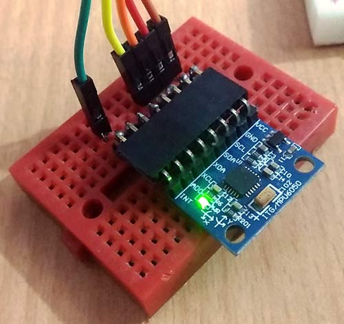
Pin Configuration:
Vcc:- this pin is used for powering the MPU6050 module with respect to ground
GND:- this is ground pin
SDA:-SDA pin is used for data between controller and mpu6050 module
SCL:- SCL pin is used for clock input
XDA:- This is sensor I2C SDA Data line for configuring and reading from external sensors ((optional) not used in our case)
XCL:- This is sensor I2C SCL clock line for configuring and reading from external sensors ((optional) not used in our case)
ADO:- I2C Slave Address LSB (not applicable in our case)
INT:- Interrupt pin for indication of data ready.
Description:
In this article, we are showing temperature, gyro and accelerometer readings over LCD using MPU6050 with Arduino. This module gives us row values and normalized values in output but row values are not stable so here we have showing normalized values over LCD. If you just want accelerometer value, you can also use Accelerometer ADXL335 with Arduino.
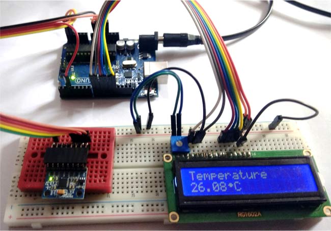
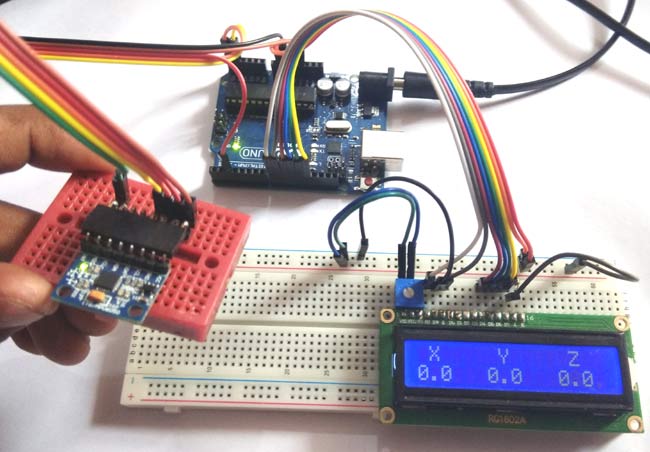
In this project, we have first shown a temperature value over LCD and after 10 seconds we show gyro values and after 10 seconds we have accelerometer readings as shown in the images below:
Circuit Diagram and Explanation:
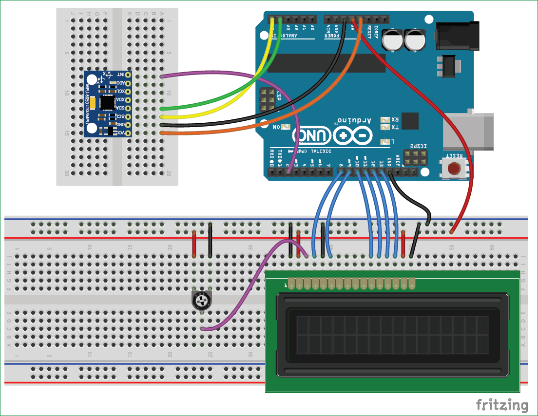
The circuit diagram, for interfacing MPU6050 with Arduino, is very simple here we have used an LCD and MPU6050. And here we have used a laptop USB power supply. A 10k pot is used for controlling the brightness of the LCD. In connection with MPU6050, we have done 5 connections in which we have connected the 3.3v power supply and ground of MPU6050 to the 3.3v and ground of Arduino. SCL and SDA pins of MPU6050 is connected with Arduino’s A4 and A5 pin. And INT pin of MPU6050 is connected to interrupt 0 of Arduino (D2). LCD’s RS, RW and EN are directly connected to 8, gnd and 9 of Arduino. Data pin are directly connected to digital pin number 10, 11, 12 and 13.
Programming Explanation:
Programming part is also easy for this project. Here we have used this MPU6050 library to interface it with Arduino. So first of all, we need to download the MPU6050 library from GitHub and install it in Arduino IDE.
After it, we can find example codes in the example. The user may test that code by directly uploading them to Arduino and can see values over serial monitor. Or the user may use our code given at the end of the article to show values over LCD and serial monitor as well.
In coding, we have included some required libraries like MPU6050 and LCD.
#include<LiquidCrystal.h>
LiquidCrystal lcd(8,9,10,11,12,13);
#include <Wire.h>
#include <MPU6050.h>
In setup function, we initialize both devices and write welcome message over LCD
void setup()
{
  lcd.begin(16,2);
  lcd.createChar(0, degree);
  Serial.begin(9600);
  Serial.println("Initialize MPU6050");
  while(!mpu.begin(MPU6050_SCALE_2000DPS, MPU6050_RANGE_2G))
  {
    lcd.clear();
    lcd.print("Device not Found");
    Serial.println("Could not find a valid MPU6050 sensor, check wiring!");
    delay(500);
  }
  count=0;
  mpu.calibrateGyro();
  mpu.setThreshold(3);
void loop()
{
    lcd.clear();
    lcd.print("Temperature");
    long st=millis();
    Serial.println("Temperature");
    while(millis()<st+period)
    {
      lcd.setCursor(0,1);
      tempShow();
    }
    lcd.clear();
    lcd.print("Gyro");
    delay(2000);
    st=millis();
    Serial.println("Gyro");
    while(millis()<st+period)
    {
      lcd.setCursor(0,1);
      gyroShow();
    }
    lcd.clear();
    lcd.print("Accelerometer");
    delay(2000);
    st=millis();
MPU6050 gyro and accelerometer both are used to detect the position and orientation of any device. Gyro uses earth gravity to determine the x,y and z-axis positions and accelerometer detects based on the rate of the change of movement. We already used the accelerometer with Arduino in many of our projects like:
- Accelerometer Based Hand Gesture Controlled Robot
- Arduino Based Vehicle Accident Alert System
- Earthquake Detector Alarm using Arduino
Complete Project Code
#include
LiquidCrystal lcd(8,9,10,11,12,13);
#include
#include
#define period 10000
MPU6050 mpu;
int count=0;
char okFlag=0;
byte degree[8] = {
0b00000,
0b00110,
0b01111,
0b00110,
0b00000,
0b00000,
0b00000,
0b00000
};
void setup()
{
lcd.begin(16,2);
lcd.createChar(0, degree);
Serial.begin(9600);
Serial.println("Initialize MPU6050");
while(!mpu.begin(MPU6050_SCALE_2000DPS, MPU6050_RANGE_2G))
{
lcd.clear();
lcd.print("Device not Found");
Serial.println("Could not find a valid MPU6050 sensor, check wiring!");
delay(500);
}
count=0;
mpu.calibrateGyro();
mpu.setThreshold(3);
lcd.clear();
lcd.print("MPU6050 Interface");
lcd.setCursor(0,1);
lcd.print(" Circuit Digest");
delay(2000);
lcd.clear();
}
void loop()
{
lcd.clear();
lcd.print("Temperature");
long st=millis();
Serial.println("Temperature");
while(millis()
lcd.setCursor(0,1);
tempShow();
}
lcd.clear();
lcd.print("Gyro");
delay(2000);
st=millis();
Serial.println("Gyro");
while(millis()
lcd.setCursor(0,1);
gyroShow();
}
lcd.clear();
lcd.print("Accelerometer");
delay(2000);
st=millis();
Serial.println("Accelerometer");
while(millis()
lcd.setCursor(0,1);
accelShow();
}
}
void tempShow()
{
float temp = mpu.readTemperature();
Serial.print(" Temp = ");
Serial.print(temp);
Serial.println(" *C");
lcd.clear();
lcd.print("Temperature");
lcd.setCursor(0,1);
lcd.print(temp);
lcd.write((byte)0);
lcd.print("C");
delay(400);
}
void gyroShow()
{
//lcd.setCursor(0,0);
lcd.clear();
lcd.print(" X Y Z");
Vector rawGyro = mpu.readRawGyro();
Vector normGyro = mpu.readNormalizeGyro();
lcd.setCursor(0,1);
lcd.print(normGyro.XAxis,1);
lcd.setCursor(6,1);
lcd.print(normGyro.YAxis,1);
lcd.setCursor(12,1);
lcd.print(normGyro.ZAxis,1);
Serial.print(" Xnorm = ");
Serial.print(normGyro.XAxis);
Serial.print(" Ynorm = ");
Serial.print(normGyro.YAxis);
Serial.print(" Znorm = ");
Serial.println(normGyro.ZAxis);
delay(200);
}
void accelShow()
{
// lcd.setCursor(0,0);
lcd.clear();
lcd.print(" X Y Z");
Vector rawAccel = mpu.readRawAccel();
Vector normAccel = mpu.readNormalizeAccel();
lcd.setCursor(0,1);
lcd.print(normAccel.XAxis,1);
lcd.setCursor(6,1);
lcd.print(normAccel.YAxis,1);
lcd.setCursor(12,1);
lcd.print(normAccel.ZAxis,1);
Serial.print(" Xnorm = ");
Serial.print(normAccel.XAxis);
Serial.print(" Ynorm = ");
Serial.print(normAccel.YAxis);
Serial.print(" Znorm = ");
Serial.println(normAccel.ZAxis);
delay(200);
}
Comments
Did you use the same library
Did you use the same library mentioned in the article
It should be a contrast
It should be a contrast problem. Adjust the pot and try
I copied your code its
I copied your code its working upto LCD coding after that its not working why is this happening
error
error in this line: while(!mpu.begin(MPU6050_SCALE_2000DPS, MPU6050_RANGE_2G))
messgae error
WARNING: Category 'Math' in library Average is not valid. Setting to 'Uncategorized'
C:\Users\Labo EEE DIB\Documents\Arduino\gyro_acc\gyro_acc.ino: In function 'void setup()':
gyro_acc:32:14: error: 'class MPU6050' has no member named 'begin'
while(!mpu.begin(MPU6050_SCALE_2000DPS, MPU6050_RANGE_2G))
^
gyro_acc:32:20: error: 'MPU6050_SCALE_2000DPS' was not declared in this scope
while(!mpu.begin(MPU6050_SCALE_2000DPS, MPU6050_RANGE_2G))
^
gyro_acc:32:43: error: 'MPU6050_RANGE_2G' was not declared in this scope
while(!mpu.begin(MPU6050_SCALE_2000DPS, MPU6050_RANGE_2G))
^
gyro_acc:41:7: error: 'class MPU6050' has no member named 'calibrateGyro'
mpu.calibrateGyro();
^
gyro_acc:42:7: error: 'class MPU6050' has no member named 'setThreshold'
mpu.setThreshold(3);
^
C:\Users\Labo EEE DIB\Documents\Arduino\gyro_acc\gyro_acc.ino: In function 'void tempShow()':
gyro_acc:89:22: error: 'class MPU6050' has no member named 'readTemperature'
float temp = mpu.readTemperature();
^
C:\Users\Labo EEE DIB\Documents\Arduino\gyro_acc\gyro_acc.ino: In function 'void gyroShow()':
gyro_acc:107:3: error: 'Vector' was not declared in this scope
Vector rawGyro = mpu.readRawGyro();
^
gyro_acc:108:10: error: expected ';' before 'normGyro'
Multiple libraries were found for "MPU6050.h"
Vector normGyro = mpu.readNormalizeGyro();
Used: C:\Users\Labo EEE DIB\Documents\Arduino\libraries\MPU6050
^
Not used: C:\Users\Labo EEE DIB\Documents\Arduino\libraries\Arduino-MPU6050-master
gyro_acc:110:13: error: 'normGyro' was not declared in this scope
lcd.print(normGyro.XAxis,1);
^
C:\Users\Labo EEE DIB\Documents\Arduino\gyro_acc\gyro_acc.ino: In function 'void accelShow()':
gyro_acc:129:3: error: 'Vector' was not declared in this scope
Vector rawAccel = mpu.readRawAccel();
^
gyro_acc:130:10: error: expected ';' before 'normAccel'
Vector normAccel = mpu.readNormalizeAccel();
^
gyro_acc:132:13: error: 'normAccel' was not declared in this scope
lcd.print(normAccel.XAxis,1);
^
exit status 1
'class MPU6050' has no member named 'begin'
I think you are using a
I think you are using a different version of the MPU6050 library. Try removing the exiting one and then add the one mentioned in this article



iin this code "begin is not a member of mpu6050 class" this error is showing and many more members are not included in this class