The Arduino Development Platform was originally developed in 2005 as an easy-to-use programmable device for art design projects. Its intention was to help non-engineers to work with basic electronics and microcontrollers without much programming knowledge. But then, because of its easy to use nature it was soon adapted by electronics beginners and hobbyists around the world and today it is even preferred for prototype development and POC developments.
While it is okay to begin with Arduino, it is important to slowly move into the core microcontrollers like AVR, ARM, PIC, STM, etc. and program it using their native applications. This is because the Arduino Programming language is very easy to understand as most of the work is done by pre-built functions like digitalWrite(), AnalogWrite(), Delay(), etc. while the low level machine language is hidden behind them. The Arduino programs are not similar to other Embedded C coding where we deal with register bits and make them high or low based on the logic of our program.
Arduino Timers without delay:
Hence, to understand what is happening inside the pre-built functions we need to dig behind these terms. For example when a delay() function is used it actual sets the Timer and Counter Register bits of the ATmega microcontroller.
In this arduino timer tutorial we are going to avoid the usage of this delay() function and instead actually deal with the Registers themselves. The good thing is you can use the same Arduino IDE for this. We will set our Timer register bits and use the Timer Overflow Interrupt to toggle an LED every time the interrupt occurs. The preloader value of the Timer bit can also be adjusted using pushbuttons to control the duration in which the interrupt occurs.
What is TIMER in Embedded Electronics?
Timer is kind of interrupt. It is like a simple clock which can measure time interval of an event. Every microcontroller has a clock (oscillator), say in Arduino Uno it is 16Mhz. This is responsible for speed. Higher the clock frequency higher will be the processing speed. A timer uses counter which counts at certain speed depending upon the clock frequency. In Arduino Uno it takes 1/16000000 seconds or 62nano seconds to make a single count. Meaning Arduino moves from one instruction to another instruction for every 62 nano second.
Timers in Arduino UNO:
In Arduino UNO there are three timers used for different functions.
Timer0:
It is an 8-Bit timer and used in timer function such as delay(), millis().
Timer1:
It is a 16-Bit timer and used in servo library.
Timer2:
It is an 8-Bit Timer and used in tone() function.
Arduino Timer Registers
To change the configuration of the timers, timer registers are used.
1. Timer/Counter Control Registers (TCCRnA/B):
This register holds the main control bits of the timer and used to control the prescalers of timer. It also allows to control the mode of timer using the WGM bits.
Frame Format:
| TCCR1A | 7 | 6 | 5 | 4 | 3 | 2 | 1 | 0 |
| COM1A1 | COM1A0 | COM1B1 | COM1B0 | COM1C1 | COM1C0 | WGM11 | WGM10 |
| TCCR1B | 7 | 6 | 5 | 4 | 3 | 2 | 1 | 0 |
| ICNC1 | ICES1 | - | WGM13 | WGM12 | CS12 | CS11 | CS10 |
Prescaler:
The CS12, CS11, CS10 bits in TCCR1B sets the prescaler value. A prescaler is used to setup the clock speed of the timer. Arduino Uno has prescalers of 1, 8, 64, 256, 1024.
| CS12 | CS11 | CS10 | USE |
| 0 | 0 | 0 | No Clock Timer STOP |
| 0 | 0 | 1 | CLCK i/o /1 No Prescaling |
| 0 | 1 | 0 | CLK i/o /8 (From Prescaler) |
| 0 | 1 | 1 | CLK i/o /64 (From Prescaler) |
| 1 | 0 | 0 | CLK i/o /256 (From Prescaler) |
| 1 | 0 | 1 | CLK i/o /1024 (From Prescaler) |
| 1 | 1 | 0 | External clock source on T1 Pin. Clock on falling edge |
| 1 | 1 | 1 | External Clock source on T1 pin. Clock on rising edge. |
2. Timer/Counter Register (TCNTn)
This Register is used to control the counter value and to set a preloader value.
Formula for preloader value for required time in second:
TCNTn = 65535 – (16x1010xTime in sec / Prescaler Value)
To calculate preloader value for timer1 for time of 2 Sec:
TCNT1 = 65535 – (16x1010x2 / 1024) = 34285
Arduino Timer Interrupts
Timer Overflow Interrupt:
Whenever the timer reaches to its maximum value say for example (16 Bit-65535) the Timer Overflow Interrupt occurs. So, an ISR interrupt service routine is called when the Timer Overflow Interrupt bit enabled in the TOIEx present in timer interrupt mask register TIMSKx.
ISR Format:
ISR(TIMERx_OVF_vect)
{
}
Output Compare Register (OCRnA/B):
Here when the Output Compare Match Interrupt occurs then the interrupt service ISR (TIMERx_COMPy_vect) is called and also OCFxy flag bit will be set in TIFRx register. This ISR is enabled by setting enable bit in OCIExy present in TIMSKx register. Where TIMSKx is Timer Interrupt Mask Register.
Timer Input Capture:
Next when the timer Input Capture Interrupt occurs then the interrupt service ISR (TIMERx_CAPT_vect) is called and also the ICFx flag bit will be set in TIFRx (Timer Interrupt Flag Register). This ISR is enabled by setting the enable bit in ICIEx present in TIMSKx register.
Components Required
- Arduino UNO
- Push Buttons (2)
- LED (Any Color)
- 10k Resistor (2), 2.2k (1)
- 16x2 LCD Display
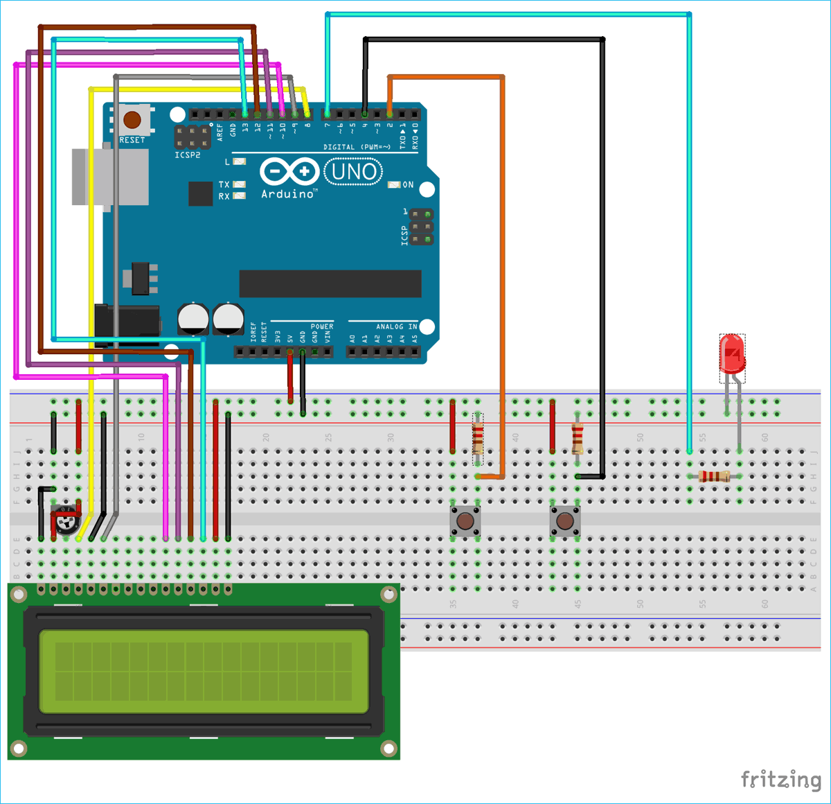
Circuit Diagram
Circuit Connections between Arduino UNO and 16x2 LCD display:
|
16x2 LCD |
Arduino UNO |
|
VSS |
GND |
|
VDD |
+5V |
|
V0 |
To potentiometer centre pin for contrast control of LCD |
|
RS |
8 |
|
RW |
GND |
|
E |
9 |
|
D4 |
10 |
|
D5 |
11 |
|
D6 |
12 |
|
D7 |
13 |
|
A |
+5V |
|
K |
GND |
Two Push buttons with pull down resistors of 10K are connected with the Arduino pins 2 & 4 and a LED is connected to PIN 7 of Arduino through a 2.2K resistor.
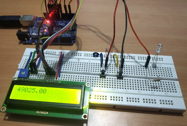
The setup will look like below image.

Programming Arduino UNO Timers
In this tutorial we will use the TIMER OVERFLOW INTERRUPT and use it to blink the LED ON and OFF for certain duration by adjusting the preloader value (TCNT1) using pushbuttons. Complete code for Arduino Timer is given at the end. Here we are explaining the code line by line:
As 16x2 LCD is used in the project to display the preloader value, so liquid crystal library is used.
#include<LiquidCrystal.h>
The LED anode pin that is connected with Arduino pin 7 is defined as ledPin.
#define ledPin 7
Next the object for accessing Liquid Crystal class is declared with the LCD pins (RS, E, D4, D5, D6, D7) that are connected with Arduino UNO.
LiquidCrystal lcd(8,9,10,11,12,13);
Then set the preloader value 3035 for 4 seconds. Check the formula above to calculate the preloader value.
float value = 3035;
Next in void setup(), first set the LCD in 16x2 mode and display a welcome message for few seconds.
  lcd.begin(16,2);
  lcd.setCursor(0,0);
  lcd.print("ARDUINO TIMERS");
  delay(2000);
  lcd.clear();
Next set the LED pin as OUTPUT pin and the Push buttons are set as INPUT pins
  pinMode(ledPin, OUTPUT);
  pinMode(2,INPUT);
  pinMode(4,INPUT);
Next disable all the interrupts:
noInterrupts();
Next the Timer1 is initialized.
TCCR1A = 0;
TCCR1B = 0;
The preloader timer value is set (Initially as 3035).
TCNT1 = value;
Then the Pre scaler value 1024 is set in the TCCR1B register.
TCCR1B |= (1 << CS10)|(1 << CS12);
The Timer overflow interrupt is enabled in the Timer Interrupt Mask register so that the ISR can be used.
TIMSK1 |= (1 << TOIE1);
At last all interrupts are enabled.
interrupts();
Now write the ISR for Timer Overflow Interrupt which is responsible for turning LED ON and OFF using digitalWrite. The state changes whenever the timer overflow interrupt occurs.
ISR(TIMER1_OVF_vect)
{
  TCNT1 = value;
  digitalWrite(ledPin, digitalRead(ledPin) ^ 1);
}
In the void loop() the value of preloader is incremented or decremented by using the push button inputs and also the value is displayed on 16x2 LCD.
  if(digitalRead(2) == HIGH)
  {
    value = value+10;             //Incement preload value
  }
  if(digitalRead(4)== HIGH)
  {
    value = value-10;            //Decrement preload value
  }
  lcd.setCursor(0,0);
  lcd.print(value);
}
So this is how a timer can be used to produce delay in Arduino program. Check the video below where we have demonstrated the change in delay by increasing and decreasing the preloader value using Push buttons.
Complete Project Code
#include<LiquidCrystal.h>            //LCD display library
#define ledPin 7
LiquidCrystal lcd(8,9,10,11,12,13);
float value = 3035;                   //Preload timer value (3035 for 4 seconds)
void setup()
{
  lcd.begin(16,2);
  lcd.setCursor(0,0);
  lcd.print("ARDUINO TIMERS");
  delay(2000);
  lcd.clear();
  pinMode(ledPin, OUTPUT);
  pinMode(2,INPUT);
  pinMode(4,INPUT);
  noInterrupts();                       // disable all interrupts
  TCCR1A = 0;
  TCCR1B = 0;
  TCNT1 = value;                        // preload timer
  TCCR1B |= (1 << CS10)|(1 << CS12);    // 1024 prescaler
  TIMSK1 |= (1 << TOIE1);               // enable timer overflow interrupt ISR
  interrupts();                         // enable all interrupts
}
ISR(TIMER1_OVF_vect)                    // interrupt service routine for overflow
{
  TCNT1 = value;                                // preload timer
  digitalWrite(ledPin, digitalRead(ledPin) ^ 1);  //Turns LED ON and OFF
}
void loop()
{
  if(digitalRead(2) == HIGH)
  {
    value = value+10;             //Incement preload value
  }
  if(digitalRead(4)== HIGH)
  {
    value = value-10;            //Decrement preload value
  }
  lcd.setCursor(0,0);
  lcd.print(value);
}
Comments
Your code does not work. No
Your code does not work. No matter if you increase or decrease the timer value it always remains at 4 seconds. In your video it is same as I mentioned. Wondering why did you put this code when you can see that it is not working.
Wrong TCNT1 Formula
I think that expression to have the TCNT1 value is wrong.
TCNT1 = 65535 – (16x106x2 / 1024) = 34285
Arduino has a 16 Mhz clock and not 16Ghz. Also Arduino 3.3V have a 8MHz clock.


Arduino: 1.8.11 (Mac OS X), Board: "Arduino Uno"
Sketch uses 3820 bytes (11%) of program storage space. Maximum is 32256 bytes.
Global variables use 77 bytes (3%) of dynamic memory, leaving 1971 bytes for local variables. Maximum is 2048 bytes.
avrdude: ser_open(): can't open device "/dev/cu.usbmodem141401": No such file or directory
Problem uploading to board. See http://www.arduino.cc/en/Guide/Troubleshooting#upload for suggestions.
This report would have more information with
"Show verbose output during compilation"
option enabled in File -> Preferences.