Fitness bands are getting very popular nowadays, which not only counts the footsteps but also tracks your calories burned, display heartbeat rate, showtime and many more. And these IoT devices are synced with the cloud so that you can easily get all the history of your physical activity on a smartphone. We have also built an IoT Based Patient Monitoring System where the critical data have been sent to ThingSpeak to be monitored from anywhere.
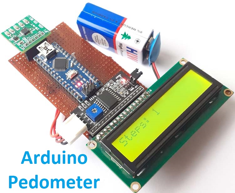
Pedometers are the devices that only used to count footsteps. So in this tutorial, we are going to build an easy and cheap DIY Pedometer using Arduino and accelerometer. This Pedometer will count the number of footsteps and display them on a 16x2 LCD module. This pedometer can be integrated with this Arduino Smart Watch.
Components Required
- Arduino Nano
- ADXL 335 Accelerometer
- 16*2 LCD
- LCD I2C Module
- Battery
ADXL335 Accelerometer
The ADXL335 is a complete 3-axis Analog accelerometer, and it works on the principle of capacitive sensing. It is a small, thin, low power module with a polysilicon surface-micro machined sensor and signals conditioning circuitry. ADXL335 accelerometer can measure the static as well as dynamic acceleration. Here in this Arduino Pedometer project, the ADXL335 accelerometer will act as a Pedometer sensor.
An Accelerometer is a device which can convert acceleration in any direction to its respective variable voltage. This is accomplished by using capacitors (refer image), as the Accel moves, the capacitor present inside it, will also undergo changes (refer image) based on the movement, since the capacitance is varied, a variable voltage can also be obtained.
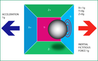
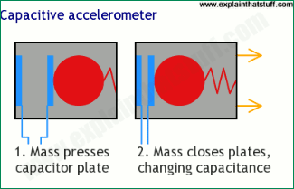
Below are the images for Accelerometer from the front and back side along with the pin description-
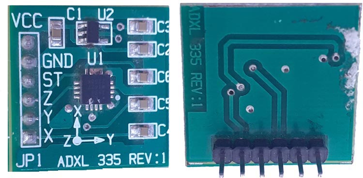
Pin Description of accelerometer:
- Vcc- 5 volt supply should connect at this pin.
- X-OUT- This pin gives an Analog output in x direction
- Y-OUT- This pin give an Analog Output in y direction
- Z-OUT- This pin gives an Analog Output in z direction
- GND- Ground
- ST- This pin used for set sensitivity of sensor
We build many projects using Accelerometer ADXL335 including Gesture controlled robot, Earthquake Detector Alarm, Ping Pong Game, etc.
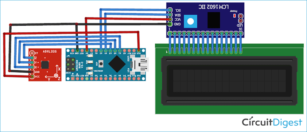
Circuit Diagram
Circuit Diagram for Arduino Accelerometer Step Counter is given below.
In this circuit, we are interfacing with Arduino Nano with ADXL335 Accelerometer. X, Y, and Z pins of the accelerometer are connected with Analog pins (A1, A2 & A3) of Arduino Nano. To interface 16x2 LCD modules with Arduino, we are using the I2C module. SCL & SDA pins of the I2C module are connected to A5 and A4 pins of Arduino Nano, respectively. Complete connections are given in the below table:
| Arduino Nano | ADXL335 |
| 3.3V | VCC |
| GND | GND |
| A1 | X |
| A2 | Y |
| A3 | Z |
| Arduino Nano | LCD I2C Module |
| 5V | VCC |
| GND | GND |
| A4 | SDA |
| A5 | SCL |
We first built this Pedometer using Arduino setup on a breadboard

And after successful testing we replicated it on Perfboard by soldering all the component on Perfboard as shown below:
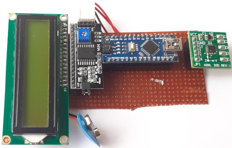
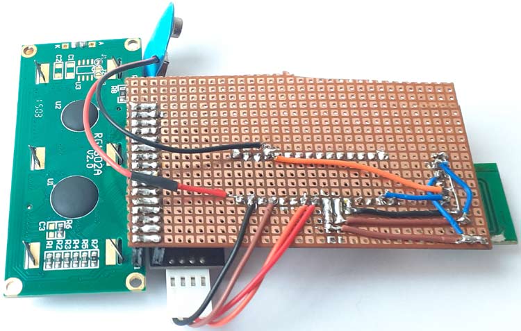
How Pedometer Works?
A pedometer calculates the total no of steps taken by a person using the three components of motion that are forward, vertical, and side. The pedometer system uses an accelerometer to get these values. Accelerometer continuously updates the maximum and minimum values of the 3-axis acceleration after every defined no. of samples. The average value of these 3-axis (Max + Min)/2, is called the dynamic threshold level, and this threshold value is used to decide whether the step is taken or not.
While running, the pedometer can be in any orientation, so the pedometer calculates the steps using the axis whose acceleration change is the largest.
Now let me give you a quick walkthrough of the working of this Arduino Pedometer:
- Firstly the pedometer starts the calibration as soon as it gets powered.
- Then in the void loop function, it continuously gets the data from X, Y, and Z-axis.
- After that, it calculates the total acceleration vector from the starting point.
- Acceleration vector is the square root (x^2+y^2+z^2) of the X, Y, and Z-axis values.
- Then it compares the average acceleration values with the threshold values to count the step number.
- If the acceleration vector crosses the threshold value, then it increases the step count; otherwise, it discards the invalid vibrations.
Programming the Arduino Step Counter
The complete Arduino Step Counter Code is given at the end of this document. Here we are explaining some important snippets of this code.
As usual, start the code by including all the required libraries. ADXL335 accelerometer does not require any library as it gives an analog output.
#include <LiquidCrystal_I2C.h>
After that, define the Arduino Pins, where the accelerometer is connected.
const int xpin = A1;
const int ypin = A2;
const int zpin = A3;
Define the threshold value for the accelerometer. This threshold value will be compared with the acceleration vector to calculate the number of steps.
float threshold = 6;
Inside the void setup, function calibrates the system when it is powered.
calibrate();
Inside the void loop function, it will read the X, Y and Z-axis values for 100 samples.
for (int a = 0; a < 100; a++)
  {
    xaccl[a] = float(analogRead(xpin) - 345);
    delay(1);
    yaccl[a] = float(analogRead(ypin) - 346);
    delay(1);
    zaccl[a] = float(analogRead(zpin) - 416);
    delay(1);
After getting the 3-axis values, calculate the total acceleration vector by taking the square root of X, Y, and Z-axis values.
totvect[a] = sqrt(((xaccl[a] - xavg) * (xaccl[a] - xavg)) + ((yaccl[a] - yavg) * (yaccl[a] - yavg)) + ((zval[a] - zavg) * (zval[a] - zavg)));
Then calculate the average of the maximum and minimum acceleration vector values.
totave[a] = (totvect[a] + totvect[a - 1]) / 2 ;
Now compare the average acceleration with the threshold. If the average is greater than the threshold, then increase the step count and raise the flag.
if (totave[a] > threshold && flag == 0)
    {
      steps = steps + 1;
      flag = 1; }
If the average is greater than the threshold but the flag is raised, then do nothing.
else if (totave[a] > threshold && flag == 1)
    {
      // Don’t Count
    }
If the total average is less than threshold and flag is raised, then put the flag down.
if (totave[a] < threshold   && flag == 1)
    {
      flag = 0;
    }
Print the number of steps on serial monitor and LCD.
Serial.println(steps );
lcd.print("Steps: ");
lcd.print(steps);
Testing the Arduino Pedometer
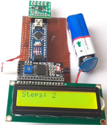
Once your hardware and code are ready, connect the Arduino to the laptop and upload the code. Now take the pedometer setup in your hands and start walking step by step, it should display the number of steps on LCD. Sometimes it increases the number of steps when pedometer vibrates very rapidly or very slowly.
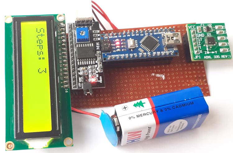
The complete working video and code for the ADXL335 pedometer Arduino are given below.
Complete Project Code
#include

LiquidCrystal_I2C lcd(0x27, 16, 2);

const int xpin = A1;

const int ypin = A2;

const int zpin = A3;

byte p[8] = {

  0x1F,

  0x1F,

  0x1F,

  0x1F,

  0x1F,

  0x1F,

  0x1F,

  0x1F

};

float threshold = 6;

float xval[100] = {0};

float yval[100] = {0};

float zval[100] = {0};

float xavg, yavg, zavg;

int steps, flag = 0;

void setup()

{

  Serial.begin(9600);

  lcd.begin();

  lcd.backlight();

  lcd.clear();

  calibrate();

}

void loop()

{

  for (int w = 0; w < 16; w++) {

    lcd.write(byte(0));

    delay(500);

  }

  int acc = 0;

  float totvect[100] = {0};

  float totave[100] = {0};

  float xaccl[100] = {0};

  float yaccl[100] = {0};

  float zaccl[100] = {0};

  for (int a = 0; a < 100; a++)

  {

    xaccl[a] = float(analogRead(xpin) - 345);

    delay(1);

    yaccl[a] = float(analogRead(ypin) - 346);

    delay(1);

    zaccl[a] = float(analogRead(zpin) - 416);

    delay(1);

    totvect[a] = sqrt(((xaccl[a] - xavg) * (xaccl[a] - xavg)) + ((yaccl[a] - yavg) * (yaccl[a] - yavg)) + ((zval[a] - zavg) * (zval[a] - zavg)));

    totave[a] = (totvect[a] + totvect[a - 1]) / 2 ;

    Serial.println("totave[a]");

    Serial.println(totave[a]);

    delay(100);

    if (totave[a] > threshold && flag == 0)

    {

      steps = steps + 1;

      flag = 1;

    }

    else if (totave[a] > threshold && flag == 1)

    {

      // Don't Count

    }

    if (totave[a] < threshold   && flag == 1)

    {

      flag = 0;

    }

    if (steps < 0) {

      steps = 0;

    }

    Serial.println('\n');

    Serial.print("steps: ");

    Serial.println(steps);

    lcd.print("Steps: ");

    lcd.print(steps);

    delay(1000);

    lcd.clear();

  }

  delay(1000);

}

void calibrate()

{

  float sum = 0;

  float sum1 = 0;

  float sum2 = 0;

  for (int i = 0; i < 100; i++) {

    xval[i] = float(analogRead(xpin) - 345);

    sum = xval[i] + sum;

  }

  delay(100);

  xavg = sum / 100.0;

  Serial.println(xavg);

  for (int j = 0; j < 100; j++)

  {

    yval[j] = float(analogRead(ypin) - 346);

    sum1 = yval[j] + sum1;

  }

  yavg = sum1 / 100.0;

  Serial.println(yavg);

  delay(100);

  for (int q = 0; q < 100; q++)

  {

    zval[q] = float(analogRead(zpin) - 416);

    sum2 = zval[q] + sum2;

  }

  zavg = sum2 / 100.0;

  delay(100);

  Serial.println(zavg);

}
Comments
For testing you can use
For testing you can use Serial monitor and if you want to send data to laptop then use esp wi-fi shield and send data to webpage
Hey, can you please explain
Hey, can you please explain what does these lines mean? Why are they being executed?
analogRead(xpin) - 345,analogRead(ypin) - 346,analogRead(zpin) - 416 and
totvect[a] = sqrt(((xaccl[a] - xavg) * (xaccl[a] - xavg)) + ((yaccl[a] - yavg) * (yaccl[a] - yavg)) + ((zval[a] - zavg) * (zval[a] - zavg)));
totave[a] = (totvect[a] + totvect[a - 1]) / 2 ;
and why are we calculating the average of the axes values for 100 values in the calibrate loop?
This is my first time working with circuits & hardware, so kindly please explain in detail.
Hoping to hear from you soon.



Hello,
Would it be possible to use a laptop as a screen instead of the LCD screen?
Hope to hear from you asap.
Regards, Maarten