Today any average car consists of around 60 to 100 sensor units in it for sensing and exchanging information. With car manufactures constantly making their car more smarter with features like Autonomous driving, Airbag system, Tire Pressure monitoring, Cruise control system etc. this number is only expected to go high. Unlike other sensors, these sensors process critical information and hence the data from these sensors should be communicated using standard automotive communication protocols. For example, cruise control system data like speed, throttle position etc are vital values which is sent to Electronic Control Unit (ECU) to decide the acceleration level of the car, a miscommunication or loss of data here could lead to critical failures. Hence unlike standard communication protocols like UART, SPI or I2C, designers use much reliable automobile communication protocols like LIN, CAN, FlexRay etc.
Out of all the available protocols CAN is more predominantly used and popular. We have already discussed what is CAN and how CAN works. So, in this article we will look into the basics again and then finally we will also exchange data between two Arduinos using CAN communication. Sounds interesting right! So, let’s get started.
Introduction to CAN
CAN a.k.a Controller Area Network is a serial communication bus designed for industrial and automotive applications. It is a message-based protocol used for communication between multiple devices. When multiple CAN devices are connected together like shown below, the connection forms a network acting like our central nervous system allowing any device to speak with any other device in the node.
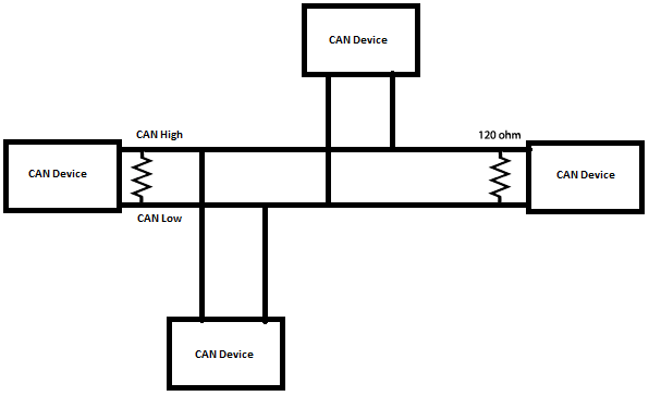
A CAN Network will consist of only two wires CAN High and CAN Low for bi-directional data transmission as shown above. Typically the communication speed for CAN ranges from 50 Kbps to 1Mbps and the distance can range from 40 meters at 1Mbps to 1000 meters at 50kpbs.
Format of CAN Message:
In the CAN communication the data is transmitted in the network as a particular message format. This message format contains of many segments but two main segments are the identifier and data which helps to send and respond to messages in CAN bus.
Identifier or CAN ID: The identifier is also known as a CAN ID or also known as PGN (Parameter Group Number). It is used to identify the CAN devices present in a CAN network. The length of the identifier is either 11 or 29 bits based on the type of CAN protocol used.
Standard CAN: 0-2047 (11-bit)
Extended CAN: 0-229-1 (29-bit)
Data: This is the actual sensor/control data that has to be send form one device to another. The size data can be anywhere from 0 to 8 bytes in length.
Data Length Code (DLC): 0 to 8 for the number of data bytes present.
Wires used in CAN:
CAN protocol consist of two wires namely CAN_H and CAN_L to send and receive information. Both the wires acts as a differential line, meaning the CAN signal (0 or 1) is represented by the potential difference between CAN_L and CAN_H. If the difference is positive and larger than a certain minimum voltage then it is 1 and if the difference is negative it is a 0.
Normally a twisted pair cable is used for CAN communication. A single 120-ohm resistor is generally used at the two ends of the CAN network as shown in image, this is because the line needs to be balanced and tied to same potential.
Comparison of CAN over SPI & I2C
Since we have already learnt how to use SPI with Arduino and IIC with Arduino, let us compare the features of SPI and I2C with CAN
| Parameter | SPI | I2C | CAN |
| Speed | 3Mbps to 10Mbps | Standard: 100Kbps | 10KBps to 1MBps Also depends upon length of wire used |
| Fast: 400 Kbps | |||
| Highspeed:3.4Mbps | |||
| Type | Synchronous | Synchronous | Asynchronous |
| Number of Wires | 3+ (MISO, MOSI, SCK, SS1, SS2…SS(n)) | 2 wires (SDA, SCL) | 2 wires (CAN_H, CAN_L) |
| Duplex | Full Duplex | Half Duplex | Half Duplex |
CAN Protocol Applications
- Because of the robustness and reliability of CAN protocol, they are used in industries like Automotive, Industrial machines, Agriculture, Medical Equipment etc.
- As wiring complexity is reduced in CAN they are mainly used in automotive applications like car.
- Low cost to implement and also hardware components price is also less.
- Easy to add and remove the CAN bus devices.
How to use CAN protocol in Arduino
As Arduino doesn’t contain any inbuilt CAN port, a CAN module called MCP2515 is used. This CAN module is interfaced with Arduino by using the SPI communication. Let’s see about more about MCP2515 in detail and how it is interfaced with Arduino.
MCP2515 CAN Module:
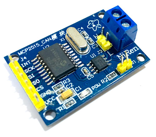
MCP2515 Module has a CAN controller MCP2515 which is high speed CAN transceiver. The connection between MCP2515 and MCU is through SPI. So, it is easy to interface with any microcontroller having SPI interface.
For beginners who want to learn CAN Bus, this module will act as a good start. This CAN SPI board is ideal for industrial automation, home automation and other automotive embedded projects.
Features and Specification of MCP2515:
- Uses High-speed CAN transceiver TJA1050
- Dimension: 40×28mm
- SPI control for expand Multi CAN bus interface
- 8MHZ crystal oscillator
- 120Ω terminal resistance
- Has independent key, LED indicator, Power indicator
- Supports 1 Mb/s CAN operation
- Low current standby operation
- Up to 112 nodes can be connected
Pinout of MCP2515 CAN Module:
|
Pin Name |
USE |
|
VCC |
5V Power input pin |
|
GND |
Ground pin |
|
CS |
SPI SLAVE select pin (Active low) |
|
SO |
SPI master input slave output lead |
|
SI |
SPI master output slave input lead |
|
SCLK |
SPI Clock pin |
|
INT |
MCP2515 interrupt pin |
In this tutorial let’s see how to send humidity & temperature (DHT11) sensor data from Arduino Nano to Arduino Uno via CAN bus module MCP2515.
Components Required
- Arduino UNO
- Arduino NANO
- DHT11
- 16x2 LCD Display
- MCP2515 CAN Module – 2
- 10k Potentiometer
- Breadboard
- Connecting Wires
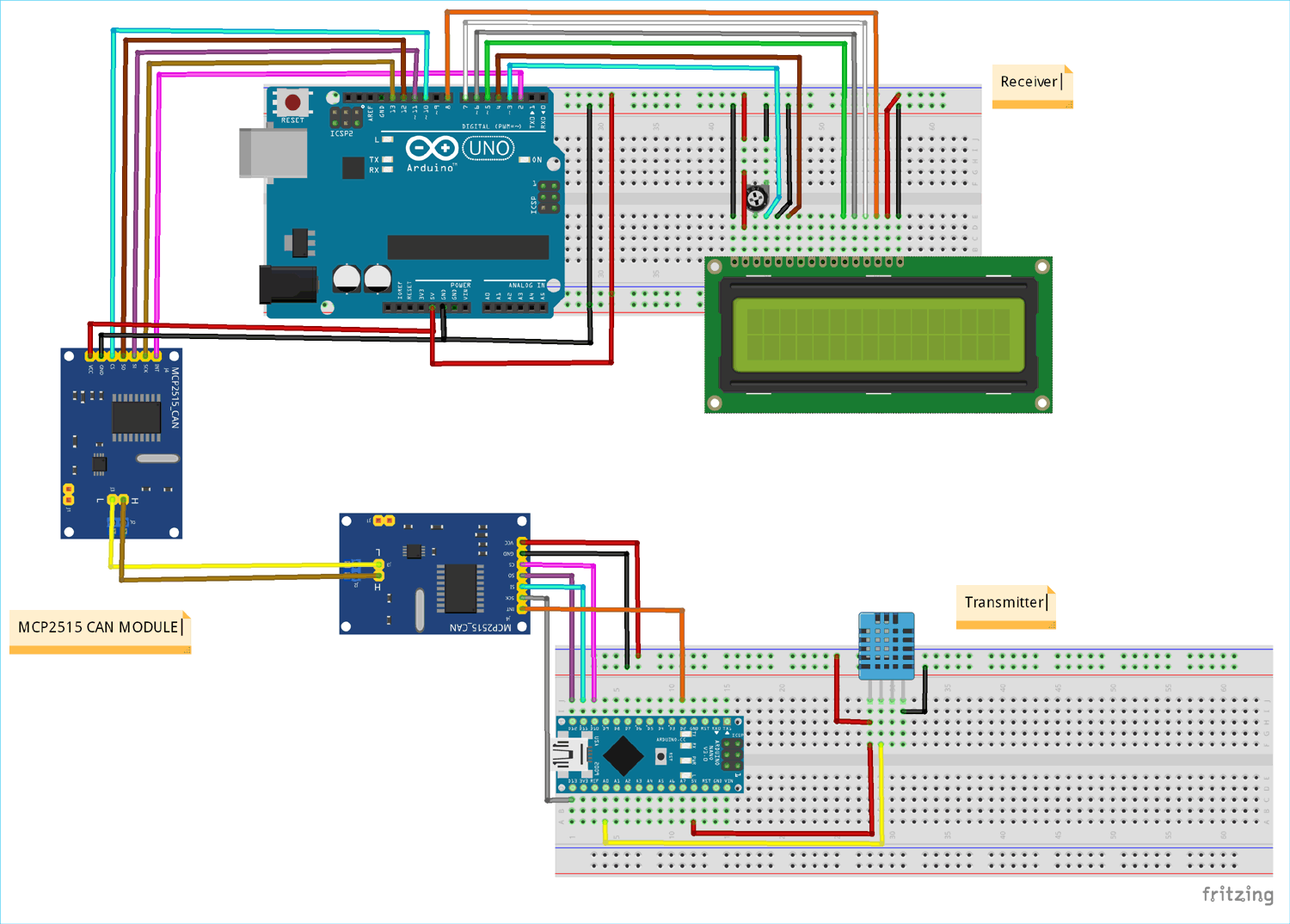
MCP2515 Arduino Circuit Diagram
Connection on CAN Transmitter side:
|
Component - Pin |
Arduino Nano |
|
MPC2515 - VCC |
+5V |
|
MPC2515 - GND |
GND |
|
MPC2515 - CS |
D10 (SPI_SS) |
|
MPC2515 - SO |
D12 (SPI_MISO) |
|
MPC2515 - S I |
D11 (SPI_MOSI) |
|
MPC2515 - SCK |
D13 (SPI_SCK) |
|
MPC2515 - INT |
D2 |
|
DHT11 - VCC |
+5V |
|
DHT11 - GND |
GND |
|
DHT11 - OUT |
A0 |
Circuit Connections at CAN Receiver side:
|
Component - Pin |
Arduino UNO |
|
MPC2515 - VCC |
+5V |
|
MPC2515 - GND |
GND |
|
MPC2515 - CS |
10 (SPI_SS) |
|
MPC2515 - SO |
12 (SPI_MISO) |
|
MPC2515 - SI |
11 (SPI_MOSI) |
|
MPC2515 - SCK |
13 (SPI_SCK) |
|
MPC2515 - INT |
2 |
|
LCD - VSS |
GND |
|
LCD - VDD |
+5V |
|
LCD - V0 |
To 10K Potentiometer Centre PIN |
|
LCD - RS |
3 |
|
LCD - RW |
GND |
|
LCD - E |
4 |
|
LCD - D4 |
5 |
|
LCD - D5 |
6 |
|
LCD - D6 |
7 |
|
LCD - D7 |
8 |
|
LCD - A |
+5V |
|
LCD - K |
GND |
Connection between two MCP2515 CAN modules
H – CAN High
L – CAN Low
|
MCP2515 (Arduino Nano) |
MCP2515 (Arduino UNO) |
|
H |
H |
|
L |
L |
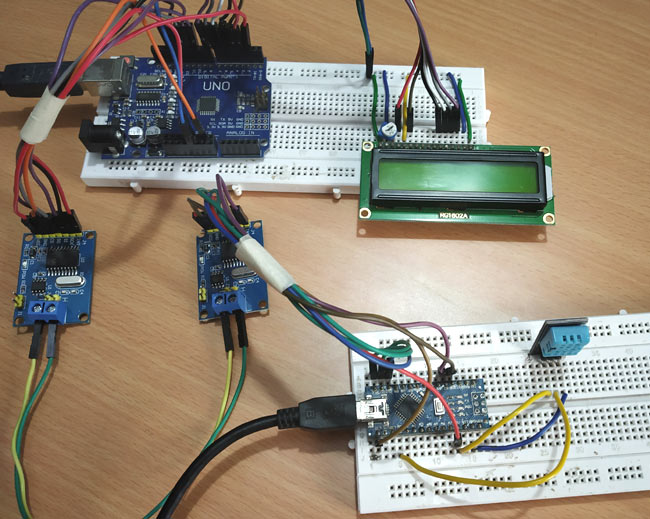
Once all the connections were made, my hardware looked like this below
Programming Arduino for CAN communication
First we have to install a library for CAN in Arduino IDE. Interfacing MCP2515 CAN Module with the Arduino becomes easier by using the following library.
- Download the ZIP file of Arduino CAN MCP2515 Library.
- From the Arduino IDE: Sketch -> Include Library -> Add .ZIP Library
In this tutorial coding is divided into two parts one as CAN transmitter code (Arduino Nano) and other as CAN Receiver code (Arduino UNO) both of which can be found at the bottom of this page. The explanation for the same is as follows.
Before writing program for sending and receiving data make sure you have installed the library following the above steps and the CAN module MCP2515 is initialized in your program as following.
Initialize MCP2515 CAN Module:
In order to create connection with MCP2515 follow the steps:
1. Set the pin number where SPI CS is connected (10 by default)
MCP2515 mcp2515(10);
2. Set baud rate and oscillator frequency
mcp2515.setBitrate(CAN_125KBPS, MCP_8MHZ);
Available Baud Rates:
CAN_5KBPS, CAN_10KBPS, CAN_20KBPS, CAN_31K25BPS, CAN_33KBPS, CAN_40KBPS, CAN_50KBPS, CAN_80KBPS, CAN_83K3BPS, CAN_95KBPS, CAN_100KBPS, CAN_125KBPS, CAN_200KBPS, CAN_250KBPS, CAN_500KBPS, CAN_1000KBPS.
Available Clock Speeds:
MCP_20MHZ, MCP_16MHZ, MCP_8MHZ
3. Set modes.
mcp2515.setNormalMode();
mcp2515.setLoopbackMode();
mcp2515.setListenOnlyMode();
CAN Transmitter Side Code Explanation (Arduino Nano)
In the transmitter section, Arduino Nano interfaced with the MCP2515 CAN module through SPI pins and DHT11 sends Temperature and Humidity data to CAN bus.
First the required libraries are included, SPI Library for using SPI Communication, MCP2515 Library for using CAN Communication and DHT Library for using DHT sensor with Arduino. We previously interfaced DHT11 with Arduino.
#include <SPI.h>
#include <mcp2515.h>
#include <DHT.h>
Now the pin name of DHT11 (OUT pin) that is connected with the A0 of Arduino Nano is defined
#define DHTPIN A0
And also, the DHTTYPE is defined as DHT11.
#define DHTTYPE DHT11
A canMsg struct data type for storing CAN message format.
struct can_frame canMsg;
Set the pin number where SPI CS is connected (10 by default)
MCP2515 mcp2515(10);
And also, object dht for class DHT with DHT pin with Arduino Nano and DHT type as DHT11 is initialized.
DHT dht(DHTPIN, DHTTYPE);
Next in void setup():
Begin the SPI communication by using following statement
SPI.begin();
And then use below statement to begin to receive Temperature and humidity values from DHT11 sensor.
dht.begin();
Next the MCP2515 is being RESET using the following command
mcp2515.reset();
Now the MCP2515 is set speed of 500KBPS and 8MHZ as clock
mcp2515.setBitrate(CAN_500KBPS,MCP_8MHZ);
And the MCP2525 is set at normal mode
mcp2515.setNormalMode();
In the void loop():
The following statement gets the Humidity and Temperature value and stores in an integer variable h and t.
 int h = dht.readHumidity();
 int t = dht.readTemperature();
Next the CAN ID is given as 0x036 (As per choice) and DLC as 8 and we give the h and t data to the data[0] and data[1] and rest all data with 0.
canMsg.can_id  = 0x036;
canMsg.can_dlc = 8;
canMsg.data[0] = h;       //Update humidity value in [0]
canMsg.data[1] = t;   //Update temperature value in [1]
canMsg.data[2] = 0x00;            //Rest all with 0
canMsg.data[3] = 0x00;
canMsg.data[4] = 0x00;
canMsg.data[5] = 0x00;
canMsg.data[6] = 0x00;
canMsg.data[7] = 0x00;
After all, to send the message to CAN BUS we use the following statement.
mcp2515.sendMessage(&canMsg);
So now the temperature and humidity data are sent as message to CAN bus.
CAN Receiver Side Code Explanation (Arduino UNO)
In the receiver section, Arduino UNO interfaced with the MCP2515 and 16x2 LCD display. Here the Arduino UNO receives the Temperature and Humidity from CAN bus and display the data received in LCD.
First the required libraries are included, SPI Library for using SPI Communication, MCP2515 Library for using CAN Communication and LiquidCrsytal Library for using 16x2 LCD with Arduino.
#include <SPI.h
#include <mcp2515.h>
#include <LiquidCrystal.h>
Next the LCD pins that are used in connecting with the Arduino UNO are defined.
const int rs = 3, en = 4, d4 = 5, d5 = 6, d6 = 7, d7 = 8;
LiquidCrystal lcd(rs, en, d4, d5, d6, d7);
A struct data type is declared for storing CAN message format.
struct can_frame canMsg;
Set the pin number where SPI CS is connected (10 by default)
MCP2515 mcp2515(10);
In void setup ():
First the LCD is set at 16x2 mode and a welcome message is displayed.
  lcd.begin(16,2);
 lcd.setCursor(0,0);
  lcd.print("CIRCUIT DIGEST");
  lcd.setCursor(0,1);
  lcd.print("CAN ARDUINO");
  delay(3000);
  lcd.clear();
Begin the SPI communication by using following statement.
SPI.begin();
Next the MCP2515 is being RESET using the following command.
mcp2515.reset();
Now the MCP2515 is set speed of 500KBPS and 8MHZ as clock.
mcp2515.setBitrate(CAN_500KBPS,MCP_8MHZ);
And the MCP2525 is set at normal mode.
mcp2515.setNormalMode();
Next in void loop():
The following statement is used to receive the message from the CAN bus. If message is received it gets into the if condition.
if (mcp2515.readMessage(&canMsg) == MCP2515::ERROR_OK)
In the if condition the data is received and stored in canMsg, the data [0] that has humidity value and data [1] that has temperature value. Both values are stored in an integer x and y.
     int x = canMsg.data[0];
     int y = canMsg.data[1];
After receiving the values, the temperature and humidity values are displayed in 16x2 LCD display using following statement.
 lcd.setCursor(0,0);
 lcd.print("Humidity : ");
 lcd.print(x);
 lcd.setCursor(0,1);
      lcd.print("Temp : ");
      lcd.print(y);
      delay(1000);
      lcd.clear();
Working of CAN communication in Arduino
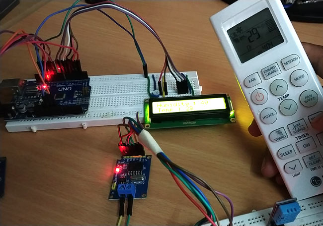
Once the hardware is ready upload the program for CAN transmitter and CAN receiver (complete programs are given below) in the respective Arduino boards. When powered you should notice the temperature value read by DHT11 will be sent to another Arduino through CAN communication and displayed on the LCD of the 2nd Arduino as you can see in the below image. I have also used my AC remote to check if the temperature displayed on the LCD is close to actual room temperature.
The complete working can be found at the video linked below. If you have any questions leave them in the comment section or use our forums for other technical questions.
Complete Project Code
CAN Transmitter Code (Arduino Nano):
#include           //Library for using SPI Communication

#include       //Library for using CAN Communication

#include           //Library for using DHT sensor
#define DHTPIN A0

#define DHTTYPE DHT11
struct can_frame canMsg;

MCP2515 mcp2515(10);
DHT dht(DHTPIN, DHTTYPE);     //initilize object dht for class DHT with DHT pin with STM32 and DHT type as DHT11
void setup()

{

  while (!Serial);

  Serial.begin(9600);


  SPI.begin();               //Begins SPI communication

  dht.begin();               //Begins to read temperature & humidity sesnor value


  mcp2515.reset();

  mcp2515.setBitrate(CAN_500KBPS,MCP_8MHZ); //Sets CAN at speed 500KBPS and Clock 8MHz

  mcp2515.setNormalMode();

}
void loop()

{

  int h = dht.readHumidity();       //Gets Humidity value

  int t = dht.readTemperature();    //Gets Temperature value
  canMsg.can_id  = 0x036;           //CAN id as 0x036

  canMsg.can_dlc = 8;               //CAN data length as 8

  canMsg.data[0] = h;               //Update humidity value in [0]

  canMsg.data[1] = t;               //Update temperature value in [1]

  canMsg.data[2] = 0x00;            //Rest all with 0

  canMsg.data[3] = 0x00;

  canMsg.data[4] = 0x00;

  canMsg.data[5] = 0x00;

  canMsg.data[6] = 0x00;

  canMsg.data[7] = 0x00;

  mcp2515.sendMessage(&canMsg);     //Sends the CAN message

  delay(1000);

}


CAN Receiver Code (Arduino UNO):
#include               //Library for using SPI Communication

#include           //Library for using CAN Communication

#include     //Library for using LCD display
const int rs = 3, en = 4, d4 = 5, d5 = 6, d6 = 7, d7 = 8;
LiquidCrystal lcd(rs, en, d4, d5, d6, d7);  //Define LCD display pins RS,E,D4,D5,D6,D7
struct can_frame canMsg;

MCP2515 mcp2515(10);                 // SPI CS Pin 10


void setup() {

  lcd.begin(16,2);                   //Sets LCD as 16x2 type

  lcd.setCursor(0,0);                //Display Welcome Message

  lcd.print("CIRCUIT DIGEST");

  lcd.setCursor(0,1);

  lcd.print("CAN ARDUINO");

  delay(3000);

  lcd.clear();


  SPI.begin();                       //Begins SPI communication


  Serial.begin(9600);                //Begins Serial Communication at 9600 baudrate


  mcp2515.reset();

  mcp2515.setBitrate(CAN_500KBPS,MCP_8MHZ); //Sets CAN at speed 500KBPS and Clock 8MHz

  mcp2515.setNormalMode();                  //Sets CAN at normal mode

}
void loop()

{

  if (mcp2515.readMessage(&canMsg) == MCP2515::ERROR_OK) // To receive data (Poll Read)

  {

     int x = canMsg.data[0];

     int y = canMsg.data[1];


      lcd.setCursor(0,0);          //Display Temp & Humidity value received at 16x2 LCD

      lcd.print("Humidity : ");

      lcd.print(x);

      lcd.setCursor(0,1);

      lcd.print("Temp : ");

      lcd.print(y);

      delay(1000);

      lcd.clear();

    }

}
Comments
It's OK. The problem was with
It's OK. The problem was with the arduino cable.
I accidently bought a Micro
I accidently bought a Micro instead of a Nano and have been trying to make this project work using the Micro. One thing I have figured out and am pretty usre I have corrected is the different pin layouts between the two boards however there still seems to be an issue with sending the canMSG over SPI to mcp2515. Is there anything differently I need to do in the software other than changing the MCP2515 mcp2515(10); to MCP2515 mcp2515(SS); ?



Hello, this project is very important for me. Unfortunately, I have a problem. I have all the parts used in the project but I can't upload the program to Arduino Nano (Transmitter). Data of Arduino Nano (Clone): Arduino Nano V3.0; Atmega 328/16Ghz; serial interface: UART, SPI, I2C; Old Bootloader. Other less complicated programs work. Anotger program from MCP2515 (standard can_write) also work.