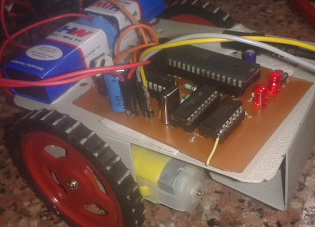
In this project we are going to build a cell phone controlled robot using 8051 microcontroller. Cell phone controlled robot runs over mobile DTMF technology. DTMF stands for Dual Tone Multiple Frequency. There are some frequencies that we use to create DTMF tones. In simple words by adding or mixing two or more frequencies we generate DTMF tone. These frequencies are given below:
In given figure we can see two groups of different frequencies. When one upper and one lower frequencies mix together then a tone is created which is called Dual Tone Multiple Frequency.
Required Components
- 8051 microcontroller
- DC Motors
- Mobile Phone
- Motor Driver L293D
- 7404
- 8870
- .1 Uf Capacitor
- 330K resistors
- 100K resistors
- 11.0592 MHz xtal
- 3.57 MHz xtal
- 22pF capacitors
- 1K resistors
- 10K resistor
- 10K resistor pack
- 33 pF capacitors
- Push button
- LEDs
- 7805
- 1000uF capacitor
- 10uF capacitors
- Copper Clad
- 9 Volt Battery
- Battery Connector
- Aux wire
- Robot Chasis with wheel
- Connecting wires
Working of Cell Phone Controlled Robot
We can divide the complete cell phone controlled robot into different sections, which are shown in the below figure.
Remote Section: This section’s main component is DTMF. Here we get a tone from the cellphone by using aux wire to DTMF Decoder IC namely HT8870 which decodes the tone into digital signal of 4bit.
Control Section: 8051 is used for controlling the complete process of this mobile phone controlled robot. 8051 reads commands sent by DTMF Decoder and compare with defined code or pattern. If commands match, the microcontroller sends respective command to driver section.
Driver Section: Driver section consists motor driver and two DC motors. Motor driver is used for driving motors because microcontroller does not supply enough voltage and current to motor. So we add a motor driver circuit to get enough voltage and current for motor. By collecting commands from 8051, motor driver drive motor according to commands.
Circuit Diagram and Explanation
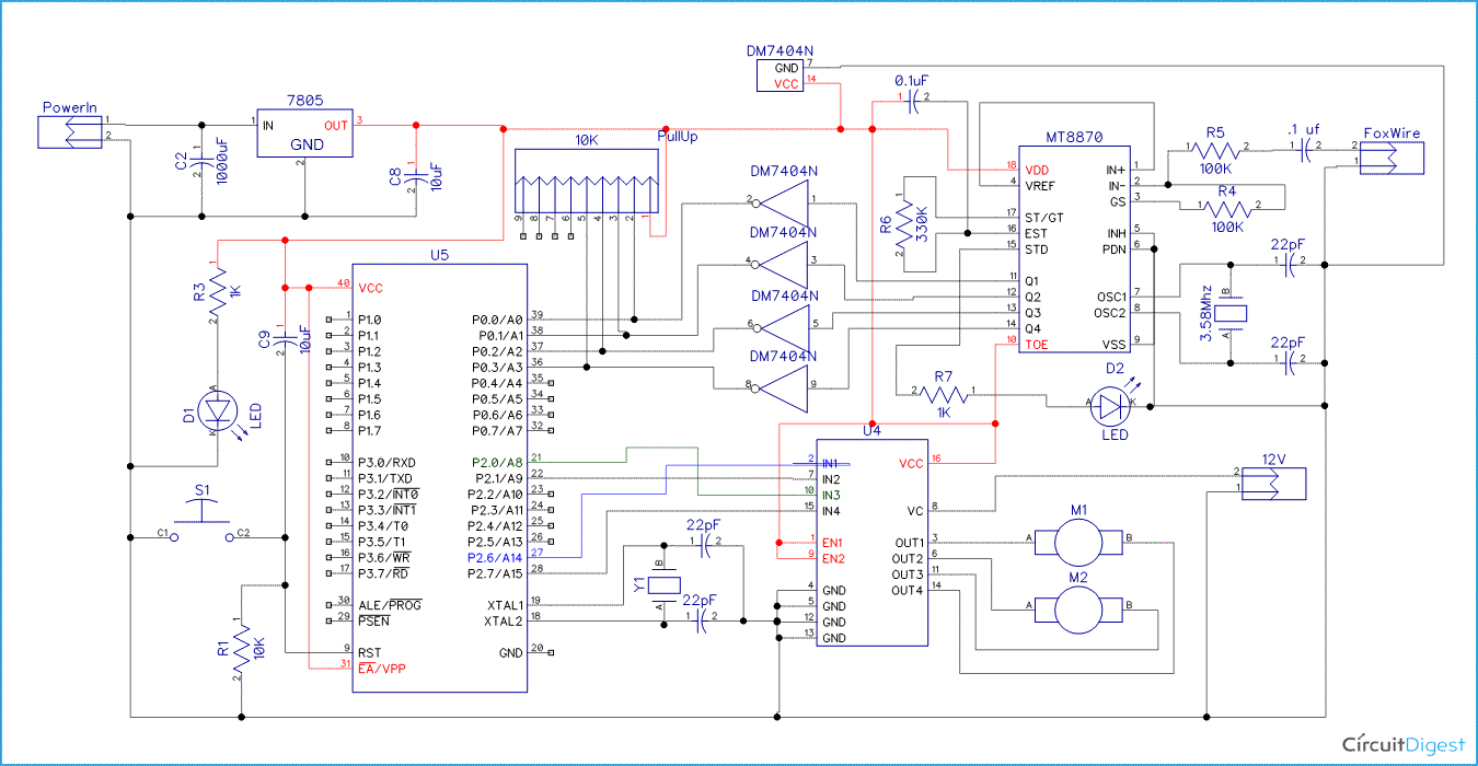
Circuit Diagram of Cell Phone Controlled Robot is very similar with our other robotics projects like PC Controlled Robot, Line Follower, Gesture Controlled Robot, etc. Here one motor driver is connected to 8051 microcontroller for driving robot. Motor driver’s input pin 2, 7, 10 and 15 are connected at 8051’s pin number P2.6, P2.3, P2.0 and P2.7 respectively. Here we have used two DC motors to drive robot in which one motor is connected at output pin of motor driver 3 and 6 and another motor is connected at 11 and 14. A 9 volt Battery is also used to power the motor driver for driving motors. A DTMF decoder is added with this circuit to fulfil our aim to control the robot with cell phone, and this decoder is plugged into a mobile phone using an aux wire for receiving command or DTMF Tone. DTMF decoder pins D0-D3 are connected with 8051’s pin number P0.0, P0.1, P0.2, P0.3 through NOT gate IC namely 7404. So 8051 will get inverted input from DTMF decoder like if we will press button ‘5’ from mobile keypad the output of DTMF decoder will be 0010 but 8051 will get 1101. Two 9 Volt batteries are used to power the circuit in which one is used for power the motors, connected at motor driver IC pin number 8, and other battery is connected to power the remaining circuit.
Cell phone controlled robot run by some commands that are send via mobile phone. We are here using DTMF function of mobile phone. Here we have used the mobile phone to show working of project. One is user mobile phone that we will call ‘remote phone’ and second one that are connected with Robot’s circuit using aux wire. This mobile phone we will call ‘Receiver Phone’.
First we make a call by using remote phone to receiver phone and then attend the call by manually or automatic answer mode. Now here is how this robot is controlled by cell phone:
When we presses ‘2’ by remote phone, robot start to moving forward and moving continues forward until next command comes.
When we presses ‘8’ by remote phone, robot change his state and start moving in backward direction until other command comes.
When we press ‘4’, Robot get turn left till next command exicuted.
When we press ‘6’, robot turned to right.
And for stopping robot we pass‘5’.
PCB Layout
Here is the PCB layout for cell phone controlled robot using 8051 microcontroller. Here you can find a tutorial to design a PCB at home with easy steps: How to make a PCB at home
Complete Project Code
#include<reg51.h>
#define key P0
#define key2 0x0d
#define key4 0x0b
#define key6 0x09
#define key8 0x07
#define key5 0x0a
#define direction P2
#define forward 0x09             //  00xx 1xx1
#define backward 0xc0
#define left 0x01
#define right 0x08
#define stop 0x00
void main()
{
 P0=0x0f;
 P2=0x00;
while(1)
{
   if(key==key2)
   direction=forward;
   else if(key==key4)
   direction=left;
   else if(key==key6)
   direction=right;
   else if(key==key8)
   direction=backward;
   else if(key==key5)
   direction=stop;
 }
}
Comments
assembly code
plz.. can you send me this code in assembly language on my email id
Is that assembly language
Is that assembly language code or c language.??
can u also send the coding to
can u also send the coding to me and every step to do it please..im lacking of ways to do my semestral project..tskk
How did you execute hex file
How did you execute hex file into this controller..?? I cant see any port to connect to computer as there is in dev board.
program of robot controlled car with microcontroller
PROGRAM
#include<reg52.h> sbit D0 = P1^0; sbit D1 = P1^1; sbit D2 = P1^2; sbit D3 = P1^3; sbit sen1=P3^6; sbit sen2=P3^7;
sbit M1_ CW =P2^0; sbit M1_ CCW = P2^1; sbit M2_ CW = P2^2; sbit M2_ CCW =P2^3; void msDelay(unsigned int x)
{
unsigned int i,j; for(i=0;i<x;i++) for(j=0;j<1275;j++);
}
void main()
{
sen1=0; sen2=0;
D0=0; D1=0; D2=0; D3=0; M1_ CW=1; M1_ CCW=1; M2_ CW=1; M2_ CCW=1; msDelay(500);
while(1)
{
if( D3==1&&D0==0&&D1==0&&D2==0&&sen1==0&&sen2==0)
{
M1_ CW=0;
M1_ CCW=1; M2_ CW=1;
M2_ CCW=0;
}
else if(D3==0&&D0==0&&D1==0&&D2==1&&sen1==0&&sen2==0)
{
M1_ CCW=0;
M1_ CW=1;
M2_ CW=0;
M2_ CCW=1;
}
else if(D3==1&&D0==0&&D1==0&&D2==1&&sen1==0&&sen2==0)
{
M1_ CCW=1;
M1_ CW=0;
M2_ CW=0; M2_ CCW=0;
}
else if(D3==0&&D0==0&&D1==1&&D2==0&&sen1==0&&sen2==0)
{
M1_ CCW=0; M1_ CW=0;
M2_ CW=1; M2_ CCW=0;
}
else if (sen1==1&&sen2==0)
{
M1_ CCW=1;
M1_ CW=0;
M2_ CW=0; M2_ CCW=0;
}
else if (sen1==0&&sen2==1)
{
M1_ CCW=0;
M1_ CW=0;
M2_ CW=1; M2_ CCW=0;
}
else if(sen1==1&&sen2==1)
{
M1_ CCW=1;
M1_ CW=1;
M2_ CW=1; M2_ CCW=1;
}
else
{
M1_ CCW=1; M1_ CW=1;
M2_ CW=1; M2_ CCW=1;
}
}
i want how to connect from Beginning to end plz help me
i want how to connect from Beginning to end with connection
Did u complete ur project ..
Did u complete ur project ...please help us if u have done it....we should submit it after 2 days...plz
Circuit Fault Detected
I noticed that the c program here says that Pin 7 or the input 2 of L293D motor driver should be connected to Port 2.3 or pin 24 of the microcontroller but In the given circuit it seems to be connected to Port 2.1 or pin 22 of the microcontroller.Please correct this fault as soon as possible.
Thanks.
Error occurred
This program contain many much error plz send tha correct program
I want to know how to connect
I want to know how to connect from starting to end can u


Give me some idea........