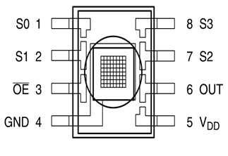
In this project we are going to interface TCS3200 color sensor with Arduino UNO. TCS3200 is a color sensor which can detect any number of colors with right programming. TCS3200 contains RGB (Red Green Blue) arrays. As shown in figure on microscopic level one can see the square boxes inside the eye on sensor. These square boxes are arrays of RGB matrix. Each of these boxes contain Three sensors, One is for sensing RED light intensity, One is for sensing GREEN light intensity and the last in for sensing BLUE light intensity.

Each of sensor arrays in these three arrays are selected separately depending on requirement. Hence it is known as programmable sensor. The module can be featured to sense the particular color and to leave the others. It contains filters for that selection purpose. There is forth mode that is no filter mode. With no filter mode the sensor detects white light.
Components Required
Hardware: ARDUINO UNO, power supply (5v), LED, JHD_162ALCD (16*2LCD),TCS3200 color sensor.
Software: ARDUINO IDE (ARDUINO nightly).
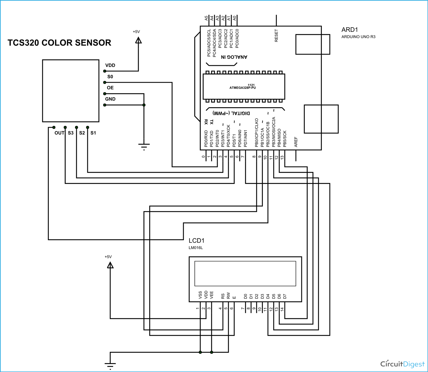
Circuit Diagram and Working Explanation
In 16x2 LCD there are 16 pins over all if there is a back light, if there is no back light there will be 14 pins. One can power or leave the back light pins. Now in the 14 pins there are 8 data pins (7-14 or D0-D7), 2 power supply pins (1&2 or VSS&VDD or GND&+5v), 3rd pin for contrast control (VEE-controls how thick the characters should be shown), and 3 control pins (RS&RW&E)
In the circuit, you can observe I have only took two control pins. The contrast bit and READ/WRITE are not often used so they can be shorted to ground. This puts LCD in highest contrast and read mode. We just need to control ENABLE and RS pins to send characters and data accordingly. [Also check: LCD interfacing with Arduino Uno]
The connections which are done for LCD are given below:
PIN1 or VSS to ground
PIN2 or VDD or VCC to +5v power
PIN3 or VEE to ground (gives maximum contrast best for a beginner)
PIN4 or RS (Register Selection) to PIN8 of ARDUINO UNO
PIN5 or RW (Read/Write) to ground (puts LCD in read mode eases the communication for user)
PIN6 or E (Enable) toPIN9 of ARDUINO UNO
PIN11 or D4 to PIN7 of ARDUINO UNO
PIN12 or D5 to PIN11 of ARDUINO UNO
PIN13 or D6 to PIN12 of ARDUINO UNO
PIN14 or D7 to PIN13 of ARDUINO UNO
The connections which are done for color sensor are given below:
VDD to +5V
GND to GROUND
OE (output Enable) to GND
S0 to UNO pin 2
S1 to UNO pin 3
S2 to UNO pin 4
S3 to UNO pin 5
OUT to UNO pin 10
The color which needs to be sensed by the color sensor is selected by two pins S2 and S3. With these two pins logic control we can tell sensor which color light intensity is to be measured.
Say we need to sense the RED color intensity we need to set both pins to LOW. Once that is done the sensor detects the intensity and sends the value to the control system inside the module.
|
S2 |
S3 |
Photodiode Type |
|
L |
L |
Red |
|
L |
H |
Blue |
|
H |
L |
Clear (no filter) |
|
H |
H |
Green |
The control system inside the module is shown in figure. The light intensity measured by array is sent to current to frequency converter. What it does is, it puts out a square wave whose frequency is in relation to current sent by ARRAY.

So we have a system which sends out a square wave whose frequency depends on light intensity of color which is selected by S2 and S3.
The signal frequency sent by module can be modulated depending on use. We can change the output signal frequency bandwidth.
|
S0 |
S1 |
Output Frequency Scaling (f0) |
|
L |
L |
Power Down |
|
L |
H |
2% |
|
H |
L |
20% |
|
H |
H |
100% |
The frequency scaling is done by two bits S0 and S1. For convenience we are going to limit the frequency scaling to 20%. This is done by setting S0 to high and S1 to LOW. This feature comes in handy when we are using the module on system with low clock.
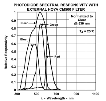
The Array sensitivity to color is shown in below figure.

Although different colors have different sensitivity, for a normal use it won’t make much difference.
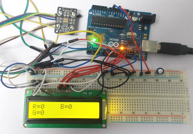
The UNO here send signal to module to detect colors and the data received by the module is shown in the 16*2 LCD connected to it.
The UNO detects three color intensities separately and shows them on LCD.
The Uno can detect the signal pulse duration by which we can get the frequency of square wave sent by module. With the frequency at hand we can match it with color on sensor.
|
As by above condition the UNO reads pulse duration on 10th pin of UNO and stores it value in “frequency” integer.
We are going to do this for all three colors for color recognition. All three color intensities are shown by frequencies on 16x2 LCD.
Complete Project Code
int OutPut= 10;//naming pin10 of uno as output
unsigned int frequency = 0;
#include <LiquidCrystal.h>
// initialize the library with the numbers of the interface pins
LiquidCrystal lcd(8, 9, 7, 11, 12, 13);//RS,EN,D4,D5,D6,D7
void setup()
{
                // set up the LCD's number of columns and rows
                lcd.begin(16, 2);
                pinMode(2, OUTPUT);
                pinMode(3, OUTPUT);//PINS 2, 3,4,5 as OUTPUT
                pinMode(4, OUTPUT);
                pinMode(5, OUTPUT);
                pinMode(10, INPUT);//PIN 10 as input
                digitalWrite(2,HIGH);
                digitalWrite(3,LOW);//setting frequency selection to 20%
}
void loop()
{
                lcd.print("R=");//printing name
                digitalWrite(4,LOW);
                digitalWrite(5,LOW);//setting for RED color sensor
                frequency = pulseIn(OutPut, LOW);//reading frequency
                lcd.print(frequency);//printing RED color frequency
                lcd.print("  ");
                lcd.setCursor(7, 0);//moving courser to position 7
                delay(500);
               lcd.print("B=");// printing name
                digitalWrite(4,LOW);
                digitalWrite(5,HIGH);// setting for BLUE color sensor
                frequency = pulseIn(OutPut, LOW);// reading frequency
                lcd.print(frequency);// printing BLUE color frequency
                lcd.print("  ");
                lcd.setCursor(0, 1);
                delay(500);
               lcd.print("G=");// printing name
                digitalWrite(4,HIGH);
                digitalWrite(5,HIGH);// setting for GREEN color sensor
                frequency = pulseIn(OutPut, LOW);// reading frequency
                lcd.print(frequency);// printing GREEN color frequency
                lcd.print("    ");
                lcd.setCursor(0, 0);
                delay(500);
}
Comments
Yes, it can detect any color
Yes, it can detect any color and gives you RGB values of that color. You can convert those RGB values into color, many online tools are available for this.
Output Frequency Scaling
Hi,
I need to understand better how you derive the "Output Frequency Scaling"; for example how you set 2% on S0 = H, S1 = L and the rest.
Please advise.
Thanks and best regards,
This is defined in Color
This is defined in Color sensor TCS3200 datasheet.
Sensor's sensing distance
What is the range of this sensor? I mean the maximum sensing distance
The sensor cannot measure
The sensor cannot measure higher distances, the maximum distance is 3cm. With the increment in distance the accuracy gets decreased.
Other sensors
Will this code work for other models of colour sensor? I use the Adafruit TCS34725 and I'm constructing a colour sensor module with an LCD screen.
what is the function of
what is the function of capacitor in this project?
Thank you very much for your replay.
Capacitor is connected across
Capacitor is connected across the power supply to filter the noise from the power supply unit.
What version of arduino is
What version of arduino is used in this project and please send me the complete tutorial.
Colour to sound conversion
Using this project idea can one then convert the colours to sound. If possible what can I add?.
Converting intensity output values to RGB values
My color sensor is giving electrical intensity as the output. How can I convert these values into RGB values of that specific color
You can detect any color with
You can detect any color with this project. Every color is made up of RGB colors, so this circuit gives you values of RGB for every color you scan.
I have just started to build
I have just started to build
Give a tutorial how to build this..
Thank u..
Can I use RGB leds to display
Can I use RGB leds to display the detected colour
Thats a good idea! yes we can
Thats a good idea! yes we can do that, but I suggest you to use NeoPixel LED to display the colors.
sory sir, , how if i want
sory sir, , how if i want showing the RGB values not the frequency , ,
TCS 3200 has a LED pin, instead of a OE Pin ?
I just bought a TCS 3200 and there is a S0..S4 pins on one end, and on the other end
5V,
GND
LED
OUT
pins - but I dont see a OE pin on my board !
I suspect that the LED pin is the OE ? Is this about right ?
Shashi
color sensor for test tube
Can this sensor be used in detecting the color of the liquid inside a test tube???
Yes, it should detect the
Yes, it should detect the color of liquid.
Yes you can program it to
Yes you can program it to only sense the particular color and leave the others and acts like a filter.
How small is the smallest color sensor with lightsourse
Hi guys, doing a project but I need a very small color sensor. Every sensor I seen so far is quite big, any idea where I can found the smallest version?
Hi can you show how much/cost
Hi can you show how much/cost you used for this project. (kindly list down for each item)
Thanks!
ask for result lcd display
with you experience unconsistence result RGB in lcd display?
Reference to library or intrinsic?
The code line,
pulseIn(OutPut, LOW);//reading frequency
Is "pulseIn()" a function from a library that needs to be brought into the Arduino IDE, or is it an intrinsic in the C# language set supported natively?
Thanks for your example and code, this is great.
Scratch that
I looked on stackoverflow.com which has a lot of great arduino info, and believe I have confirmed that indeed PulseIn() is part of the C# implementation.
Hi, this tutorial was
Hi, this tutorial was extremely helpful and I cannot thank you enough.
I want to take it a step further. Can we add a RGB LED somewhere and ask it to generate the same color as the one detected by the sensor?
So in short, Color X---> Sensor ---> Arduino ---> RGB LED ---> Color X.
How many colours???
Can it detect only three colours, if no pls tell the modifications to do so that we can detect more than 3 colours.
it can detect more than 3
it can detect more than 3 colors. if u have specific color to detect, just set the value into program
Hello Dilip,
Hello Dilip,
I have made this project. However, I find that all three values (R,G and B) are very close to each other, irrespective of what colour object is held up in front of the sensor. For example, without any object, I get R=188, B=183 & G= 190. Then when I bring a red object close to the sensor, it shows R=610, B=605 and G=620. With a blue object, I get R =676, B=670 and G = 690. Same is the case with a green object.
Can you tell me what I am doing wrong?
Thanks.
Deepak
It shows a greater value for
It shows a greater value for green even when you put red color in front of the sensor. Why does this happen?
I'm experiencing the same as
I'm experiencing the same as Saurabhh and Deepak
fluorescence color
How can i Make this circuit to detect the fluorescence color
my lcd shows boxes only it
my lcd shows boxes only it does not display output
Hi !, Thanks for this. here
Hi !, Thanks for this. here, when we measure visually red colour thing, lcd shows higher 'G' value than 'R' value & so on .How to avoid this problem ? It is a problem of tcs 3200 sensor , what is the suitable sensor ?
Thanks. Soma.
T should not happen like that
T should not happen like that try using a new sensor
i need a sensor that detects
i need a sensor that detects only green color . What would be the best one to be used?
Yes this sensor can detect
Yes this sensor can detect green color also


How many colors it can detect? Is it possible to you in for measuring skin color? Thank you for replay.