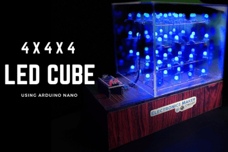
In this project, we're making a cool 4×4×4 LED cube with Arduino Nano. LED cubes, also known as LED Matrix, can light up your room, study space, or Maker area giving it a awesome cool look. Moreover it is very easy to build and helps you get creative with electronics and coding.
Our LED Cube, with dimensions of 4x4x4, consists of four layers, each containing 64 LEDs. Meaning, each layer accommodates 16 LEDs, as you can see in the diagram later in this article. The connection involves 64 LEDs linked to the Arduino in a specific combination. When the positive terminal of an LED receives a HIGH signal from the Arduino and the negative terminal obtains a LOW signal, the LED lights up. To assemble the cube, connect one pin to each column (16 in total) and one pin to each layer (4 in total). Therefore, you only require 20 pins to complete this impressive 4x4x4 LED cube project. We will guide you through a step-by-step process on constructing the four layers, ensuring the LEDs are aligned, evenly spaced, and correctly soldered in place.
Previously we have also built a 3x3x3 LED cube on Circuit Digest, if you are interested in building one check out the links below
- DIY 3X3X3 LED Cube with Arduino
- 3X3X3 LED Cube using 555 Timer and CD4020 IC
- 3X3X3 LED Cube with Raspberry Pi and Python Program
Required Components for 4×4×4 Led Cube using Arduino Nano
- Arduino Nano
- 64- 5mm blue LEDs
- Female Headers
- Rainbow Ribbon cable
- 100Ω Resistor
- 3V battery to test the LED
- Zero PCB board
- Copper wire
- Tools (Soldering iron, Wirecutter, Sandpaper)
4×4×4 Led Cube Circuit Diagram
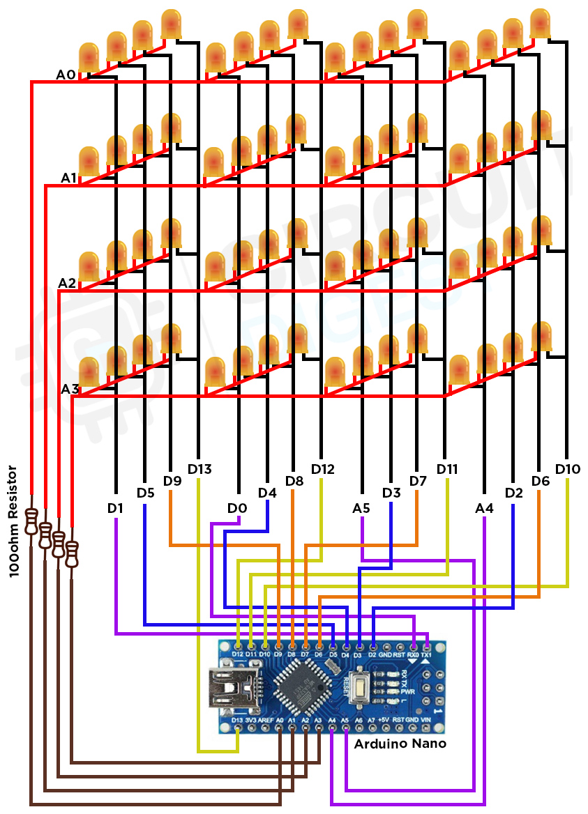
The circuit diagram for a 4 * 4 * 4 LED cube using Arduino Nano involves several components and connections to ensure proper functioning. Here's a step-by-step explanation. Arrange 64 LEDs in a 4x4x4 matrix. Each LED represents a pixel in the cube.
Connect the anode (longer leg) of each LED to its respective row, and the cathode (shorter leg) to its respective column. The complete 4x4x4 led cube schematic is shown in the image below.
Connect the digital output pins (A4 to D13) of the Arduino Nano to the columns of the LED cube. These pins will control the individual columns of the cube.
Connect the digital output pins (A0 to A3) to the layers of the cube. These pins will control each layer of the cube. Insert current-limiting resistors (typically 100-220 ohms) in series with each layer to prevent excessive current flow. Connect one end of the resistor to the digital output pins of the Arduino Nano and the other end to the respective row.
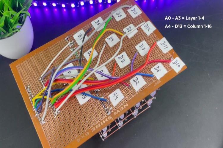
Remember to double-check your connections and use appropriate current-limiting resistors to protect the LEDs. With this setup, you can program the Arduino Nano to display various patterns and animations on your 4x4x4 LED cube.
How does 4x4x4 LED Cube Work?
Before you start soldering and get into the nitty-gritty of the project, it's super important to get a handle on how things work. The main brain behind this project is a microcontroller board called Arduino Nano. It's like a tiny computer and uses an ATmega328P microcontroller. This little guy has 20 pins that can be used for different things, like turning things on and off. In our case, we're focusing on 14 digital pins and 6 analog pins, and all of them will act as on-off switches in our project.
Now, onto the 4x4x4 LED cube it's made up of 64 LEDs arranged in a kind of grid. There are 4 layers of LEDs, and each layer has 16 LEDs in a 4x4 setup. Each LED in a layer is set up in a way that might sound a bit complicated at first; it's called common anode. This just means all the positive sides of the LEDs are connected. Now, here's the cool part even though we have 64 LEDs, we only need 20 pins on our microcontroller to control them. We use 16 pins to control the LEDs on each layer. The trick is to connect the layers through their positive sides and, by giving 5 volts to one LED and connecting the negative side to the ground, we can make it light up. The remaining 4 pins provide the power to the layers. Our programming magic will make all this work smoothly. The below image show the 4x4x4 LED Cube Arduino Simulation, you can see how each pin on arduino nano is able to control the LEDs on our cube individually.
Design and Build of 4×4×4 Led Cube using Arduino Nano
Check all 64 LEDs to make sure they work by using a small button battery.
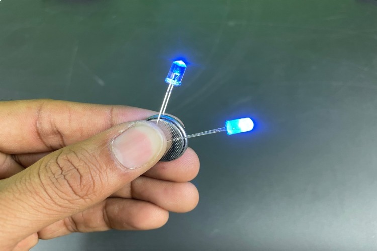
Before we start putting together our LED cube and doing any soldering, it's a good idea to make sure the LEDs are working properly. Our LEDs need 3.3 volts. The Longer lead is Positive and shorter one is Negative. You can easily test them with any 3.3V battery. I used a Lithium-Ion battery for testing in my case.
The LEDs we're using are clear and give off a very faint light, so we want to make them less intense.
Diffusing the light makes the LEDs much brighter, making the cube look cooler. Simply rub sandpaper on the top surface of each LED, or you can use a DC motor with sandpaper to diffuse all 64 LEDs.
Building a 4x4x4 LED Cube
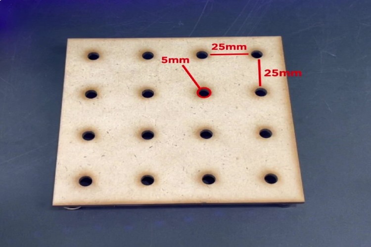
To make the template for your LED cube, get a piece of wood big enough for a 4x4 grid, making sure each square is 25mm. Start by drawing a 4x4 grid on the wood with lines. Use a center punch to make dents where the lines intersect. Then, find a drill bit that's just right – small to hold the LED in place securely, but big enough for easy removal without bending the wires. Drill the 16 holes at the points marked on the grid. Now, your LED cube template is all set and ready for the next steps in putting it together. Insert a LED into the individual holes.
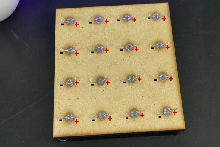
Now, take a straight copper wire and solder it to the positive pin of the LEDs in the first row, as shown in the image below. Similarly, solder the positive pins of the LEDs in all four rows in the same manner.
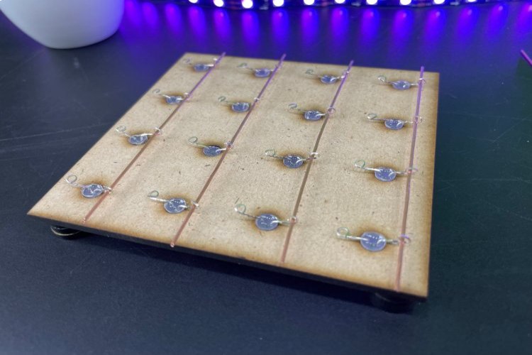
Now, proceed to join the ends of the legs on both sides of the four copper wires through soldering. This will establish a connection, linking all 16 positive legs of the LEDs to one another. By doing so, we will have successfully completed the assembly of our first layer.
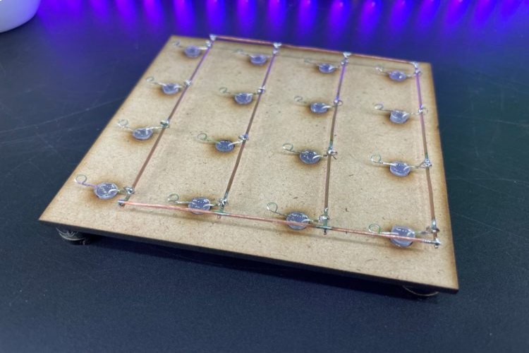
After the hole positive legs are soldered together, flip the box over and start pushing the tips of the LEDs out of the holes in the jig. Make sure to do this evenly to avoid bending or damaging the layers structure. Now your first LED layer is finished! Follow this step three more times to end up with four layers.
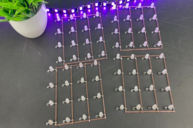
Next, take the first LED layers and solder the 16 negative leads together by stacking the individual layers on the top of each other.
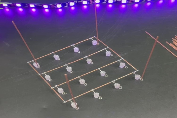
Put another layer on top and align one of the corners exactly 25mm (or whatever distance you used in your grid) above the first layer. This is the distance between the anode wires.
Hold the corner in place with a helping hand and solder the corner cathode of the first layer to the corner cathode of the second layer. Do this for all the corners.
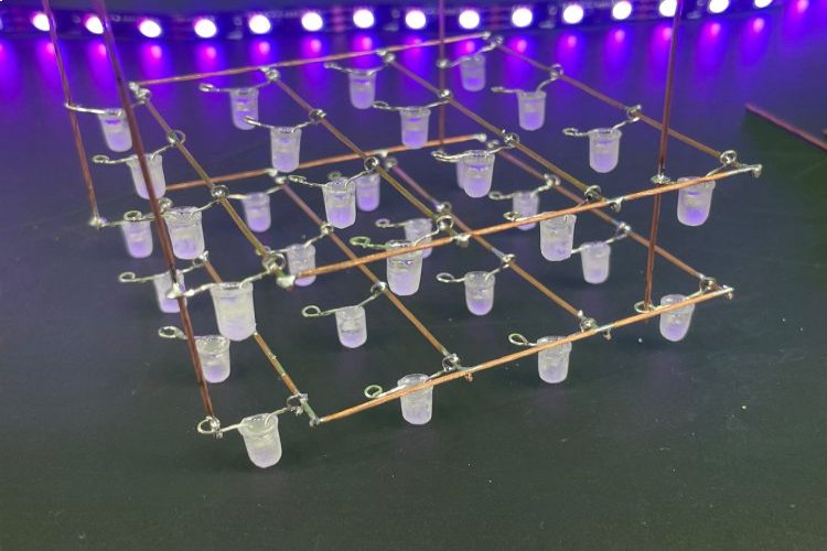
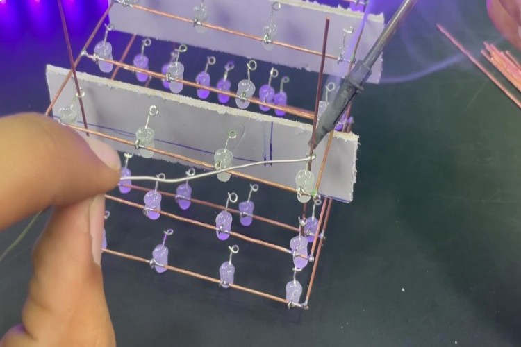
The 4x4x4 LED cube is starting to take shape. Check if the layers are perfectly aligned in all dimensions. If not, bend a little to adjust. Or re-solder if it's the height distance that's off. When they are perfectly aligned, solder the remaining 12 cathode together.
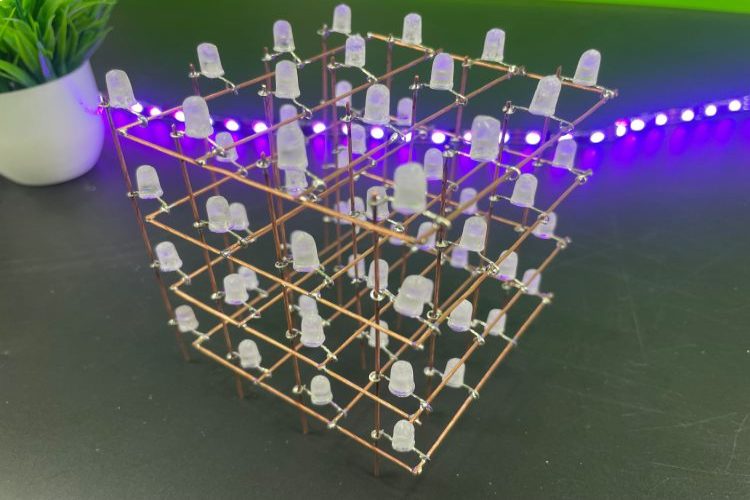
4×4×4 LED Cube Arduino Code Explanation
The code is structured to perform a sequence of predefined lighting patterns, creating an engaging visual experience on the 4x4x4 LED cube. The complete 4x4x4 led cube code is given at the bottom of this page.The animations include flickering effects, sequential LED activations, random patterns, and various dynamic displays. Users can modify the delay times and experiment with the order or create new functions to customize the LED cube's behavior.
int layer[4]={A3,A2,A1,A0}; //initialize and declaring led layers
int column[16]={13,12,11,10,9,8,7,6,5,4,3,2,1,0,A5,A4}; //initializing and declaring led rows
int time = 250;
column: An array holding the pin numbers for the columns of the LED cube.
layer: An array holding the pin numbers for the layers of the LED cube.
time: A variable representing the delay time used in various parts of the code.
void setup()
{

  for(int i = 0; i<16; i++)
  {
    pinMode(column[i], OUTPUT);  //setting rows to output
  }

  for(int i = 0; i<4; i++)
  {
    pinMode(layer[i], OUTPUT);  //setting layers to output
  }

  randomSeed(analogRead(10));  //seeding random for random pattern
}
The setup function is executed once at the beginning of the program. It sets each pin in the column and layer arrays as an output. It seeds the random number generator using an analog reading from pin 10.
void loop()
{
  turnEverythingOff();
  flickerOn();
  turnEverythingOn();
  delay(time);
  turnOnAndOffAllByLayerUpAndDownNotTimed();
  layerstompUpAndDown();
  spiralInAndOut();
  turnOnAndOffAllByColumnSideways();
  delay(time);
  aroundEdgeDown();
  turnEverythingOff();
  randomflicker();
  randomRain();
  diagonalRectangle();
  goThroughAllLedsOneAtATime();
  propeller();
  spiralInAndOut();
  flickerOff();
  turnEverythingOff();
  delay(2000);
}
The loop function is the main execution loop of the program. It calls various lighting patterns and effects in sequence, each followed by a delay of time milliseconds. The loop then waits for 2000 milliseconds (2 seconds) before starting the next iteration.
Control Funtions for 4x4x4 LED Cube Arduino Code
The code defines several functions, each responsible for a specific lighting pattern or effect. Here's a summary of some notable functions.
- turnEverythingOff(): Turns off all LEDs.
- turnEverythingOn(): Turns on all LEDs.
- flickerOn(): Gradually increases and decreases the brightness of all LEDs.
- turnOnAndOffAllByLayerUpAndDownNotTimed(): Sequentially turns on and off layers in an up-and-down pattern.
- turnOnAndOffAllByColumnSideways(): Sequentially turns on and off columns in a sideways pattern.
- layerstompUpAndDown(): Simulates a stomp effect by turning on and off a single layer.
- flickerOff(): Gradually increases and decreases the brightness of all LEDs.
- aroundEdgeDown(): Lights up LEDs around the edge of the cube in a descending pattern.
- randomflicker(): Simulates a random flickering effect.
- randomRain(): Simulates a rain effect with randomly falling LEDs.
- diagonalRectangle(): Lights up LEDs in a diagonal rectangle pattern.
- propeller(): Simulates a propeller effect.
- spiralInAndOut(): Lights up LEDs in a spiral in and out pattern.
- goThroughAllLedsOneAtATime(): Sequentially turns on and off all LEDs one at a time.
The code provides a set of functions for controlling a 4x4x4 LED cube, creating various lighting patterns and effects. Each lighting pattern is encapsulated within a function, promoting modularity and ease of understanding. The loop function orchestrates the execution of these patterns in a sequential manner.
4x4x4 LED Cube Code Generator
I get that programming the LED cube can be a real head-scratcher, especially after putting it all together. That's why this is an easy-to-use Windows app named Cube3D. This app takes the pain out of programming your LED cube. It's designed to whip up the necessary code, whether you're using Arduino or C with Atmel Studio. Right now, it's all set for a 4x4x4 LED cube. Download Cube3D application (.exe) from the link and follow the install wizard.
The application generates a pattern table for a 4x4x4 LED cube and makes it easy to visualize the patterns. The code for programming the LED cube comes with the application and also exists in its own repository LED-Cube-Code.
.jpg)
Just pick the LEDs you want to light up by clicking on them – super simple! Once you hit Enter in the code editor, it works its magic and creates a pattern based on which LEDs are turned on in the cube. It has an input field for the time variable, by changing this you change how long (in ms) a pattern will be displayed on the cube.
When the code in the editor looks just right, hit export. You've got two choices: export it as an Arduino project or just the pattern file. Opting for the Arduino project gives you a neat folder with all the Arduino code for your LED cube and the pattern.h file. Open this Arduino file in the Arduino IDE, upload the program, and boom! Your cube struts its stuff according to your custom pattern. Easy peasy! we hope that this 4x4x4 led cube project report is helpful for you to build one on your own. For more information visit CircuitDigest GitHub page below.
Complete Project Code
//4x4x4 LED Cube Code for Arduino Nano
//by CircuitDigest
  int layer[4]={A3,A2,A1,A0}; //initialize and declaring led layers
  int column[16]={13,12,11,10,9,8,7,6,5,4,3,2,1,0,A5,A4}; //initializing and declaring led rows
  int time = 250;
void setup()
{
  for(int i = 0; i<16; i++)
  {
    pinMode(column[i], OUTPUT);  //setting rows to ouput
  }
  for(int i = 0; i<4; i++)
  {
    pinMode(layer[i], OUTPUT);  //setting layers to output
  }
  randomSeed(analogRead(10));  //seeding random for random pattern
}
void loop()
{
  turnEverythingOff();
  flickerOn();
  turnEverythingOn();
  delay(time);
  turnOnAndOffAllByLayerUpAndDownNotTimed();
  layerstompUpAndDown();
  spiralInAndOut();
  turnOnAndOffAllByColumnSideways();
  delay(time);
  aroundEdgeDown();
  turnEverythingOff();
  randomflicker();
  randomRain();
  diagonalRectangle();
  goThroughAllLedsOneAtATime();
  propeller();
  spiralInAndOut();
  flickerOff();
  turnEverythingOff();
  delay(2000);
}
//turn all off
void turnEverythingOff()
 {
   for(int i = 0; i<16; i++)
   {
     digitalWrite(column[i], 1);
   }
   for(int i = 0; i<4; i++)
   {
     digitalWrite(layer[i], 0);
   }
 }
//turn all on
void turnEverythingOn()
{
  for(int i = 0; i<16; i++)
  {
    digitalWrite(column[i], 0);
  }
  //turning on layers
  for(int i = 0; i<4; i++)
  {
    digitalWrite(layer[i], 1);
  }
}
//turn columns off
void turnColumnsOff()
{
  for(int i = 0; i<16; i++)
  {
    digitalWrite(column[i], 1);
  }
}
//flicker on
void flickerOn()
{
  int i = 150;
  while(i != 0)
  {
    turnEverythingOn();
    delay(i);
    turnEverythingOff();
    delay(i);
    i-= 5;
  }
}
//turn everything on and off by layer up and down NOT TIMED
void turnOnAndOffAllByLayerUpAndDownNotTimed()
{
  int x = 75;
  for(int i = 5; i != 0; i--)
  {
    turnEverythingOn();
    for(int i = 4; i!=0; i--)
    {
      digitalWrite(layer[i-1], 0);
      delay(x);
    }
    for(int i = 0; i<4; i++)
    {
      digitalWrite(layer[i], 1);
      delay(x);
    }
      for(int i = 0; i<4; i++)
    {
      digitalWrite(layer[i], 0);
      delay(x);
    }
    for(int i = 4; i!=0; i--)
    {
      digitalWrite(layer[i-1], 1);
      delay(x);
    }
  }
}
//turn everything on and off by column sideways
void turnOnAndOffAllByColumnSideways()
{
  int x = 75;
  turnEverythingOff();
  //turn on layers
  for(int i = 0; i<4; i++)
  {
    digitalWrite(layer[i], 1);
  }
  for(int y = 0; y<3; y++)
  {
    //turn on 0-3
    for(int i = 0; i<4; i++)
    {
      digitalWrite(column[i], 0);
      delay(x);
    }
    //turn on 4-7
    for(int i = 4; i<8; i++)
    {
      digitalWrite(column[i], 0);
      delay(x);
    }
    //turn on 8-11
    for(int i = 8; i<12; i++)
    {
      digitalWrite(column[i], 0);
      delay(x);
    }
    //turn on 12-15
    for(int i = 12; i<16; i++)
    {
      digitalWrite(column[i], 0);
      delay(x);
    }
    //turn off 0-3
    for(int i = 0; i<4; i++)
    {
      digitalWrite(column[i], 1);
      delay(x);
    }
    //turn off 4-7
    for(int i = 4; i<8; i++)
    {
      digitalWrite(column[i], 1);
      delay(x);
    }
    //turn off 8-11
    for(int i = 8; i<12; i++)
    {
      digitalWrite(column[i], 1);
      delay(x);
    }
    //turn off 12-15
    for(int i = 12; i<16; i++)
    {
      digitalWrite(column[i], 1);
      delay(x);
    }
    //turn on 12-15
    for(int i = 12; i<16; i++)
    {
      digitalWrite(column[i], 0);
      delay(x);
    }
    //turn on 8-11
    for(int i = 8; i<12; i++)
    {
      digitalWrite(column[i], 0);
      delay(x);
    }
    //turn on 4-7
    for(int i = 4; i<8; i++)
    {
      digitalWrite(column[i], 0);
      delay(x);
    }
    //turn on 0-3
    for(int i = 0; i<4; i++)
    {
      digitalWrite(column[i], 0);
      delay(x);
    }
    //turn off 12-15
    for(int i = 12; i<16; i++)
    {
      digitalWrite(column[i], 1);
      delay(x);
    }
    //turn off 8-11
    for(int i = 8; i<12; i++)
    {
      digitalWrite(column[i], 1);
      delay(x);
    }
    //turn off 4-7
    for(int i = 4; i<8; i++)
    {
      digitalWrite(column[i], 1);
      delay(x);
    }
    //turn off 0-3
    for(int i = 0; i<4; i++)
    {
      digitalWrite(column[i], 1);
      delay(x);
    }
  }
}
//up and down single layer stomp
void layerstompUpAndDown()
{
  int x = 75;
  for(int i = 0; i<4; i++)
  {
    digitalWrite(layer[i], 0);
  }
  for(int y = 0; y<5; y++)
  {
    for(int count = 0; count<1; count++)
    {
      for(int i = 0; i<4; i++)
      {
        digitalWrite(layer[i], 1);
        delay(x);
        digitalWrite(layer[i], 0);
      }
      for(int i = 4; i !=0; i--)
      {
        digitalWrite(layer[i-1], 1);
        delay(x);
        digitalWrite(layer[i-1], 0);
      }
    }
    for(int i = 0; i<4; i++)
    {
      digitalWrite(layer[i], 1);
      delay(x);
    }
    for(int i = 4; i!=0; i--)
    {
      digitalWrite(layer[i-1], 0);
      delay(x);
    }
  }
}
//flicker off
void flickerOff()
{
  turnEverythingOn();
  for(int i = 0; i!= 150; i+=5)
  {
    turnEverythingOff();
    delay(i+50);
    turnEverythingOn();
    delay(i);
  }
}
//around edge of the cube down
void aroundEdgeDown()
{
  for(int x = 200; x != 0; x -=50)
  {
    turnEverythingOff();
    for(int i = 4; i != 0; i--)
    {
      digitalWrite(layer[i-1], 1);
      digitalWrite(column[5], 0);
      digitalWrite(column[6], 0);
      digitalWrite(column[9], 0);
      digitalWrite(column[10], 0);
      digitalWrite(column[0], 0);
      delay(x);
      digitalWrite(column[0], 1);
      digitalWrite(column[4], 0);
      delay(x);
      digitalWrite(column[4], 1);
      digitalWrite(column[8], 0);
      delay(x);
      digitalWrite(column[8], 1);
      digitalWrite(column[12], 0);
      delay(x);
      digitalWrite(column[12], 1);
      digitalWrite(column[13], 0);
      delay(x);
      digitalWrite(column[13], 1);
      digitalWrite(column[15], 0);
      delay(x);
      digitalWrite(column[15], 1);
      digitalWrite(column[14], 0);
      delay(x);
      digitalWrite(column[14], 1);
      digitalWrite(column[11], 0);
      delay(x);
      digitalWrite(column[11], 1);
      digitalWrite(column[7], 0);
      delay(x);
      digitalWrite(column[7], 1);
      digitalWrite(column[3], 0);
      delay(x);
      digitalWrite(column[3], 1);
      digitalWrite(column[2], 0);
      delay(x);
      digitalWrite(column[2], 1);
      digitalWrite(column[1], 0);
      delay(x);
      digitalWrite(column[1], 1);
    }
  }
}
//random flicker
void randomflicker()
{
  turnEverythingOff();
  int x = 10;
  for(int i = 0; i !=750; i+=2)
  {
  int randomLayer = random(0,4);
  int randomColumn = random(0,16);
  digitalWrite(layer[randomLayer], 1);
  digitalWrite(column[randomColumn], 0);
  delay(x);
  digitalWrite(layer[randomLayer], 0);
  digitalWrite(column[randomColumn], 1);
  delay(x);
  }
}
//random rain
void randomRain()
{
  turnEverythingOff();
  int x = 100;
  for(int i = 0; i!=60; i+=2)
  {
    int randomColumn = random(0,16);
    digitalWrite(column[randomColumn], 0);
    digitalWrite(layer[0], 1);
    delay(x+50);
    digitalWrite(layer[0], 0);
    digitalWrite(layer[1], 1);
    delay(x);
    digitalWrite(layer[1], 0);
    digitalWrite(layer[2], 1);
    delay(x);
    digitalWrite(layer[2], 0);
    digitalWrite(layer[3], 1);
    delay(x+50);
    digitalWrite(layer[3], 0);
    digitalWrite(column[randomColumn], 1);
  }
}
//diagonal rectangle
void diagonalRectangle()
{
  int x = 350;
  turnEverythingOff();
  for(int count = 0; count<5; count++)
  {
    //top left
    for(int i = 0; i<8; i++)
    {
      digitalWrite(column[i], 0);
    }
    digitalWrite(layer[3], 1);
    digitalWrite(layer[2], 1);
    delay(x);
    turnEverythingOff();
    //middle middle
    for(int i = 4; i<12; i++)
    {
      digitalWrite(column[i], 0);
    }
    digitalWrite(layer[1], 1);
    digitalWrite(layer[2], 1);
    delay(x);
    turnEverythingOff();
    //bottom right
    for(int i = 8; i<16; i++)
    {
      digitalWrite(column[i], 0);
    }
    digitalWrite(layer[0], 1);
    digitalWrite(layer[1], 1);
    delay(x);
    turnEverythingOff();
    //bottom middle
    for(int i = 4; i<12; i++)
    {
      digitalWrite(column[i], 0);
    }
    digitalWrite(layer[0], 1);
    digitalWrite(layer[1], 1);
    delay(x);
    turnEverythingOff();
    //bottom left
    for(int i = 0; i<8; i++)
    {
      digitalWrite(column[i], 0);
    }
    digitalWrite(layer[0], 1);
    digitalWrite(layer[1], 1);
    delay(x);
    turnEverythingOff();
    //middle middle
    for(int i = 4; i<12; i++)
    {
      digitalWrite(column[i], 0);
    }
    digitalWrite(layer[1], 1);
    digitalWrite(layer[2], 1);
    delay(x);
    turnEverythingOff();
    //top right
    for(int i = 8; i<16; i++)
    {
      digitalWrite(column[i], 0);
    }
    digitalWrite(layer[2], 1);
    digitalWrite(layer[3], 1);
    delay(x);
    turnEverythingOff();
    //top middle
    for(int i = 4; i<12; i++)
    {
      digitalWrite(column[i], 0);
    }
    digitalWrite(layer[2], 1);
    digitalWrite(layer[3], 1);
    delay(x);
    turnEverythingOff();
  }
  //top left
  for(int i = 0; i<8; i++)
  {
    digitalWrite(column[i], 0);
  }
  digitalWrite(layer[3], 1);
  digitalWrite(layer[2], 1);
  delay(x);
  turnEverythingOff();
}
//propeller
void propeller()
{
  turnEverythingOff();
  int x = 90;
  for(int y = 4; y>0; y--)
  {
    for(int i = 0; i<6; i++)
    {
      //turn on layer
      digitalWrite(layer[y-1], 1);
      //a1
      turnColumnsOff();
      digitalWrite(column[0], 0);
      digitalWrite(column[5], 0);
      digitalWrite(column[10], 0);
      digitalWrite(column[15], 0);
      delay(x);
      //b1
      turnColumnsOff();
      digitalWrite(column[4], 0);
      digitalWrite(column[5], 0);
      digitalWrite(column[10], 0);
      digitalWrite(column[11], 0);
      delay(x);
      //c1
      turnColumnsOff();
      digitalWrite(column[6], 0);
      digitalWrite(column[7], 0);
      digitalWrite(column[8], 0);
      digitalWrite(column[9], 0);
      delay(x);
      //d1
      turnColumnsOff();
      digitalWrite(column[3], 0);
      digitalWrite(column[6], 0);
      digitalWrite(column[9], 0);
      digitalWrite(column[12], 0);
      delay(x);
      //d2
      turnColumnsOff();
      digitalWrite(column[2], 0);
      digitalWrite(column[6], 0);
      digitalWrite(column[9], 0);
      digitalWrite(column[13], 0);
      delay(x);
      //d3
      turnColumnsOff();
      digitalWrite(column[1], 0);
      digitalWrite(column[5], 0);
      digitalWrite(column[10], 0);
      digitalWrite(column[14], 0);
      delay(x);
    }
  }
  //d4
  turnColumnsOff();
  digitalWrite(column[0], 0);
  digitalWrite(column[5], 0);
  digitalWrite(column[10], 0);
  digitalWrite(column[15], 0);
  delay(x);
}
//spiral in and out
void spiralInAndOut()
{
  turnEverythingOn();
  int x = 60;
  for(int i = 0; i<6; i++)
  {
    //spiral in clockwise
    digitalWrite(column[0], 1);
    delay(x);
    digitalWrite(column[1], 1);
    delay(x);
    digitalWrite(column[2], 1);
    delay(x);
    digitalWrite(column[3], 1);
    delay(x);
    digitalWrite(column[7], 1);
    delay(x);
    digitalWrite(column[11], 1);
    delay(x);
    digitalWrite(column[15], 1);
    delay(x);
    digitalWrite(column[14], 1);
    delay(x);
    digitalWrite(column[13], 1);
    delay(x);
    digitalWrite(column[12], 1);
    delay(x);
    digitalWrite(column[8], 1);
    delay(x);
    digitalWrite(column[4], 1);
    delay(x);
    digitalWrite(column[5], 1);
    delay(x);
    digitalWrite(column[6], 1);
    delay(x);
    digitalWrite(column[10], 1);
    delay(x);
    digitalWrite(column[9], 1);
    delay(x);
//spiral out counter clockwise
    digitalWrite(column[9], 0);
    delay(x);
    digitalWrite(column[10], 0);
    delay(x);
    digitalWrite(column[6], 0);
    delay(x);
    digitalWrite(column[5], 0);
    delay(x);
    digitalWrite(column[4], 0);
    delay(x);
    digitalWrite(column[8], 0);
    delay(x);
    digitalWrite(column[12], 0);
    delay(x);
    digitalWrite(column[13], 0);
    delay(x);
    digitalWrite(column[14], 0);
    delay(x);
    digitalWrite(column[15], 0);
    delay(x);
    digitalWrite(column[11], 0);
    delay(x);
    digitalWrite(column[7], 0);
    delay(x);
    digitalWrite(column[3], 0);
    delay(x);
    digitalWrite(column[2], 0);
    delay(x);
    digitalWrite(column[1], 0);
    delay(x);
    digitalWrite(column[0], 0);
    delay(x);
//spiral in counter clock wise
    digitalWrite(column[0], 1);
    delay(x);
    digitalWrite(column[4], 1);
    delay(x);
    digitalWrite(column[8], 1);
    delay(x);
    digitalWrite(column[12], 1);
    delay(x);
    digitalWrite(column[13], 1);
    delay(x);
    digitalWrite(column[14], 1);
    delay(x);
    digitalWrite(column[15], 1);
    delay(x);
    digitalWrite(column[11], 1);
    delay(x);
    digitalWrite(column[7], 1);
    delay(x);
    digitalWrite(column[3], 1);
    delay(x);
    digitalWrite(column[2], 1);
    delay(x);
    digitalWrite(column[1], 1);
    delay(x);
    digitalWrite(column[5], 1);
    delay(x);
    digitalWrite(column[9], 1);
    delay(x);
    digitalWrite(column[10], 1);
    delay(x);
    digitalWrite(column[6], 1);
    delay(x);
//spiral out clock wise
    digitalWrite(column[6], 0);
    delay(x);
    digitalWrite(column[10], 0);
    delay(x);
    digitalWrite(column[9], 0);
    delay(x);
    digitalWrite(column[5], 0);
    delay(x);
    digitalWrite(column[1], 0);
    delay(x);
    digitalWrite(column[2], 0);
    delay(x);
    digitalWrite(column[3], 0);
    delay(x);
    digitalWrite(column[7], 0);
    delay(x);
    digitalWrite(column[11], 0);
    delay(x);
    digitalWrite(column[15], 0);
    delay(x);
    digitalWrite(column[14], 0);
    delay(x);
    digitalWrite(column[13], 0);
    delay(x);
    digitalWrite(column[12], 0);
    delay(x);
    digitalWrite(column[8], 0);
    delay(x);
    digitalWrite(column[4], 0);
    delay(x);
    digitalWrite(column[0], 0);
    delay(x);
  }
}
//go through all leds one at a time
void goThroughAllLedsOneAtATime()
{
  int x = 15;
  turnEverythingOff();
  for(int y = 0; y<5; y++)
  {
    //0-3
    for(int count = 4; count != 0; count--)
    {
      digitalWrite(layer[count-1], 1);
      for(int i = 0; i<4; i++)
      {
        digitalWrite(column[i], 0);
        delay(x);
        digitalWrite(column[i], 1);
        delay(x);
      }
    digitalWrite(layer[count-1], 0);
    }
    //4-7
    for(int count = 0; count < 4; count++)
    {
      digitalWrite(layer[count], 1);
      for(int i = 4; i<8; i++)
      {
        digitalWrite(column[i], 0);
        delay(x);
        digitalWrite(column[i], 1);
        delay(x);
      }
    digitalWrite(layer[count], 0);
    }
    //8-11
    for(int count = 4; count != 0; count--)
    {
      digitalWrite(layer[count-1], 1);
      for(int i = 8; i<12; i++)
      {
        digitalWrite(column[i], 0);
        delay(x);
        digitalWrite(column[i], 1);
        delay(x);
      }
    digitalWrite(layer[count-1], 0);
    }
    //12-15
    for(int count = 0; count < 4; count++)
    {
      digitalWrite(layer[count], 1);
      for(int i = 12; i<16; i++)
      {
        digitalWrite(column[i], 0);
        delay(x);
        digitalWrite(column[i], 1);
        delay(x);
      }
    digitalWrite(layer[count], 0);
    }
  }
}
