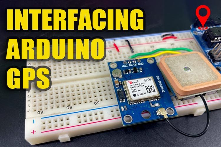
Welcome to our guide on interfacing the Arduino with the NEO-6M GPS module! In this blog, we'll delve into the step-by-step process of connecting and communicating between an Arduino board and the NEO-6M GPS module, enabling you to harness location-based data in your projects. From the important parts of the GPS module to the pinout interfacing and coding, you can find everything about Arduino GPS sensor in this article.
Components Required
Arduino Uno
Neo 6M GPS module
NEO-6M GPS module with Arduino
The neo6m GPS module typically has four main pins -VCC, GND, TX and RX. The below image shows the neo6mv2 GPS module pinout.
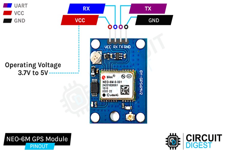
VCC: Connects to a 5V power supply.
GND: Ground connection.
TX: Transmit pin (outputs data), connects to the RX pin of the Arduino or another device (receiver).
RX: Receive pin (inputs data), connect to the TX pin of the Arduino or another device (transmitter).
How does a NEO-6M GPS Module Work?
The NEO-6M GPS module operates by receiving signals from multiple satellites orbiting Earth to determine its exact location through a process called trilateration. It utilizes a low-power GPS chipset capable of receiving signals from up to 22 satellites simultaneously. The module communicates with these satellites by using radio signals, capturing data such as the satellite's position and the time it took for the signal to travel. By analyzing this information, the NEO-6M calculates its latitude, longitude, altitude, time, and other relevant data. It interfaces with a microcontroller or a computer through serial communication(using RX and TX pins), providing accurate positioning information for various applications like navigation, mapping, tracking, and more.
NEO-6M GPS Module
The NEO-6M GPS module typically consists of several key components, the below image shows the parts of neo-6m GPS module.
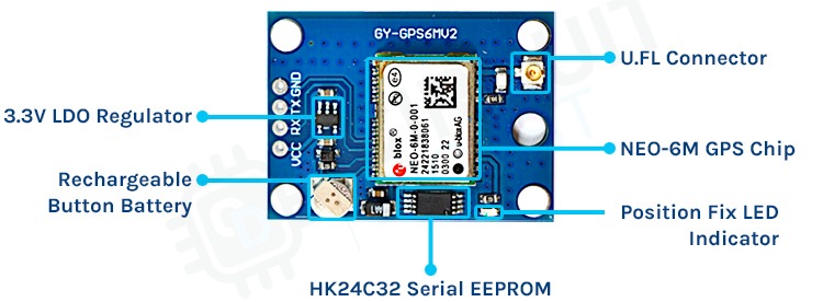
Position Fix LED Indicators: Often present to display the status of the module, indicating when it's searching for satellites, has established a fix, or is in communication with other devices.
GPS Chipset: The heart of the module, responsible for receiving signals from satellites and calculating positioning data.
Power supply components: Including 3.3V voltage regulator which helps to convert 5V signal received from the arduino to 3.3V, a few capacitors, and other similar passive components.
Battery backed RAM: - The battery backed RAM consists of two main components: -
1) HK24C32 Serial EEPROM and 2) A Rechargeable button battery.
The rechargeable battery powers the EEPROM which stores the data like clock data, latest position data and module configuration. The battery can retain data for two weeks from the EEPROM without any power.
Battery-Backed RAM in NEO-6M GPS Module
Battery-backed RAM in a NEO-6M GPS module serves as a crucial element for retaining vital data even when the main power source is disconnected. This backup capability ensures that important information, such as satellite data , last known position, time, and other critical settings, is preserved during power cycles. Since acquiring satellite data can take time and substantial resources, storing this information in battery-backed RAM ensures quicker startup times by retaining the satellite data rather than having to acquire it anew every time the module powers up.
UFL connector: This is used to connect an external antenna to the module for better signal reception.
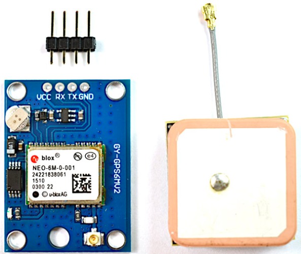
Patch Antenna: A built-in antenna designed to receive signals from GPS satellites. It helps in capturing signals effectively for accurate positioning. Below is the photo of the module with the antenna.
Commonly Asked Questions about NEO-6M GPS Module
Can I use the NEO-6M indoors?
It's challenging to get a GPS fix indoors due to weakened satellite signals. However, some modules might receive signals near windows or in areas with good signal penetration. For consistent accuracy, outdoor use is recommended.
How accurate is the NEO-6M GPS Module? What is the Arduino GPS Module Accuracy?
The NEO-6M typically provides accuracy within a few meters under ideal conditions. However, factors like signal interference, satellite visibility, and environmental obstacles can affect its accuracy.
How many satellites does the NEO-6M connect to?
The NEO-6M can connect to multiple satellites simultaneously for data acquisition. It generally requires signals from at least four satellites to calculate accurate position and time information.
Is GPS Sensor Arduino and Arduino GPS Module both same?
Yes, the Arduino GPS module is sometimes also called as GPS sensor. But the more accurate way to call it would be Arduino GPS Module.
Arduino GPS Module Circuit Diargam
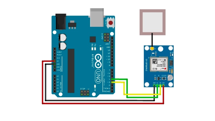
The GPS module will be connected to the arduino with the help of UART (Universal Asynchronous Receiver /Transmitter) protocol. You can check out the Arduino GPS Module wiring diagram below. If you do not want to do these connections manually you can also by the Arduino GPS Module shield, but we have kept things simple and cost-effective by simple connecting the GPS module with wire to the Arduino UNO board.
The 5V pin of the Arduino is connected to VCC of the gps module. The GND is connected to the gnd. The TX pin of the arduino is connected to the RX pin of the gps module and the RX pin of the arduino is connected to the TX pin of the gps module.
After connecting your arduino to your computer with the help of the USB cable. There can be two outputs, the below images show the led status of Arduino neo6m GPS module after it is powered.
First is that the Position Fix LED Indicator is blinking once every second which means that it has got enough satellites to give us the latitude and longitude details.
Second is that the LED is not blinking which means that you need to keep it in an open area for it to gaina signal of the satellites.
Arduino Code for NEO-6M GPS Module
This code basically sets up the communication with the GPS module, reads data, and displays relevant information like location, date, and time.
The library which you need to include before you can start uploading the code can be found in Sketch> Include> Manage Libraries and write “tinygpsplus” by Mikal Hart and then Install it. Special thanks to Mikalhart, for his awesome library
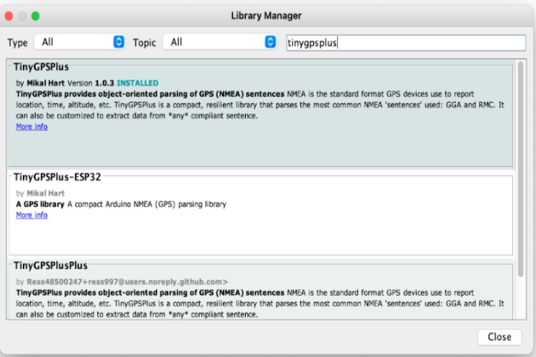
Here’s the Arduino neo6m GPS code explanation before you upload the code.
#include <TinyGPSPlus.h>
#include <SoftwareSerial.h>
This section includes the necessary libraries: TinyGPSPlus for handling GPS data and SoftwareSerial for software-based serial communication.
static const int RXPin = 3, TXPin = 2; static const uint32_t GPSBaud = 9600;
Defines constant values for the RX and TX pins for communication with the GPS module and sets the baud rate for the GPS communication.
TinyGPSPlus gps; SoftwareSerial ss(RXPin, TXPin);
Initializes the TinyGPSPlus object named gps to handle GPS data and the SoftwareSerial object named ss to communicate with the GPS module using the specified RX and TX pins.
void setup() {
Serial.begin(115200);
ss.begin(GPSBaud);
Serial.println(F("DeviceExample.ino")); // Printing information for demonstration and version of TinyGPSPlus library // by Mikal Hart }
Configures the serial communication for the Arduino board and the GPS module. It initializes the serial communication with the computer at a baud rate of 115200 and sets up the SoftwareSerial object at the defined GPS baud rate. It also prints some information about the demonstration and the version of the TinyGPSPlus library.
void loop() { while (ss.available() > 0)
{ if (gps.encode(ss.read())) { displayInfo();
}
 }
 if (millis() > 5000 && gps.charsProcessed() < 10)
{ Serial.println(F("No GPS detected: check wiring."));
while(true); }
 }
The main loop continually checks for available data from the GPS module using the SoftwareSerial object ss. If there is incoming data, it is read and processed by the gps.encode() function. If data is successfully encoded, the displayInfo() function is called to show GPS information. Additionally, it includes a check for GPS detection within a certain time frame and alerts if the GPS is not detected.
void displayInfo() {
// Displaying Google Maps link with latitude and longitude information if GPS location is valid

if (gps.location.isValid()) {

Serial.print("http://www.google.com/maps/place/");
Serial.print(gps.location.lat(), 6);
Serial.print(F(","));
Serial.println(gps.location.lng(), 6); } else { Serial.print(F("INVALID"));
 } // Displaying date and time information if valid

if (gps.date.isValid()) {

// Displaying date in MM/DD/YYYY format // If the date is invalid, it prints "INVALID"

} else

{ Serial.print(F("INVALID")); } // Displaying time in HH:MM:SS format if valid // If the time is invalid, it prints "INVALID"

}
The displayInfo() function prints GPS location information in the form of a Google Maps link (if the location is valid) containing latitude and longitude coordinates. It also displays date and time information if available in the specified formats.
Arduino Neo6m GPS Module - Working Demo
After the gps gets a fix it will look like this, and the data will be displayed on the serial monitor
Neo 6M GPS Module vs Neo 7M GPS Module
Both the NEO-6M and NEO-7M are GPS modules developed by u-blox, commonly used in various applications requiring precise location tracking. These modules are part of the NEO series and offer different features and capabilities:
NEO-6M:
It's an older module compared to the NEO-7M.
Uses u-blox's UBX-G6010 chip.
Typically has lower sensitivity and performance compared to newer modules.
Provides basic GPS functionality.
NEO-7M:
A more recent module with enhanced features compared to the NEO-6M.
Uses u-blox's UBX-G7020 chip.
Generally offers improved sensitivity and performance.
Might include additional features like support for more satellite constellations (e.g., GPS, GLONASS, Galileo).
Neo6M GPS Module Not Working?
Allow Module Initialization: If it's your first time using the GPS module, keep it powered on for a few hours. It is there to provide charge to the EEPROM and the onboard RTC.
Optimal Location: Use the GPS outdoors or near a window with minimal obstructions. This ensures better signal reception and accuracy.
Check Pin Connections: Verify that the RX (Receive) and TX (Transmit) pins are correctly connected. If problems persist, try reversing their positions to ensure proper communication.
Even after checking the above points if your GPS module is still not working, check out the Neo 6M GPs module not working troubleshooting guide article to check out the common problems with this module and how to solve them.
Arduino GPS Module Projects
Build A Low Power SMS Based Vehicle Tracking System with A9G GSM+GPS Module and Arduino
Discover how to create a low-power, efficient vehicle tracking system using the A9G GSM+GPS module and Arduino. Follow along as we delve into the step-by-step process of integrating these components to establish an SMS-based tracking system. From harnessing GPS data to leveraging GSM communication, learn how to craft a cost-effective solution for monitoring and tracing vehicles effortlessly.
IoT Based GPS Location Tracker Using NodeMCU and GPS Module – Save GPS Co-ordinates and View on Google Maps
Read this blog to know how to make a GPS tracker with NodeMCU and a GPS module. Learn to capture and store GPS coordinates, enabling seamless integration with Google Maps for visualizing real-time or historical location data. Explore how this DIY project transforms into a powerful tool for location-based tracking and mapping, empowering you to monitor and trace assets or vehicles with ease.
DIY GPS Speedometer Using Arduino and OLED
Rev up your DIY skills with Arduino and an OLED display to craft your own GPS speedometer. Dive into the world of hardware and coding as we guide you through the steps to build a personalized speedometer that retrieves GPS data and showcases real-time speed on an OLED screen. Experience the thrill of creating a custom gadget that accurately measures velocity, merging technology and creativity in this engaging project.
Complete Project Code
//Arduino GPS Module Code
#include <TinyGPSPlus.h>
#include <SoftwareSerial.h>
/*
   This sample sketch demonstrates the normal use of a TinyGPSPlus (TinyGPSPlus) object.
   It requires the use of SoftwareSerial, and assumes that you have a
   4800-baud serial GPS device hooked up on pins 4(rx) and 3(tx).
*/
static const int RXPin = 3, TXPin = 2;
static const uint32_t GPSBaud = 9600;
// The TinyGPSPlus object
TinyGPSPlus gps;
// The serial connection to the GPS device
SoftwareSerial ss(RXPin, TXPin);
void setup()
{
  Serial.begin(115200);
  ss.begin(GPSBaud);
  Serial.println(F("DeviceExample.ino"));
  Serial.println(F("A simple demonstration of TinyGPSPlus with an attached GPS module"));
  Serial.print(F("Testing TinyGPSPlus library v. ")); Serial.println(TinyGPSPlus::libraryVersion());
  Serial.println(F("by Mikal Hart"));
  Serial.println();
}
void loop()
{
  // This sketch displays information every time a new sentence is correctly encoded.
  while (ss.available() > 0)
    if (gps.encode(ss.read()))
      displayInfo();
  if (millis() > 5000 && gps.charsProcessed() < 10)
  {
    Serial.println(F("No GPS detected: check wiring."));
    while(true);
  }
}
void displayInfo()
{
  Serial.println(F("google map link below: "));
  if (gps.location.isValid())
  {
  Serial.print("http://www.google.com/maps/place/");
    Serial.print(gps.location.lat(), 6);
    Serial.print(F(","));
    Serial.println(gps.location.lng(), 6);
  }
  else
  {
    Serial.print(F("INVALID"));
  }
  Serial.print(F("Date/Time:"));
  if (gps.date.isValid())
  {
    Serial.print(gps.date.month());
    Serial.print(F("/"));
    Serial.print(gps.date.day());
    Serial.print(F("/"));
    Serial.print(gps.date.year());
  }
  else
  {
    Serial.print(F("INVALID"));
  }
  Serial.print(F(" "));
  if (gps.time.isValid())
  {
    if (gps.time.hour() < 10) Serial.print(F("0"));
    Serial.print(gps.time.hour());
    Serial.print(F(":"));
    if (gps.time.minute() < 10) Serial.print(F("0"));
    Serial.print(gps.time.minute());
    Serial.print(F(":"));
    if (gps.time.second() < 10) Serial.print(F("0"));
    Serial.print(gps.time.second());
    Serial.print(F("."));
    if (gps.time.centisecond() < 10) Serial.print(F("0"));
    Serial.print(gps.time.centisecond());
  }
  else
  {
    Serial.print(F("INVALID"));
  }
  Serial.println();
}
