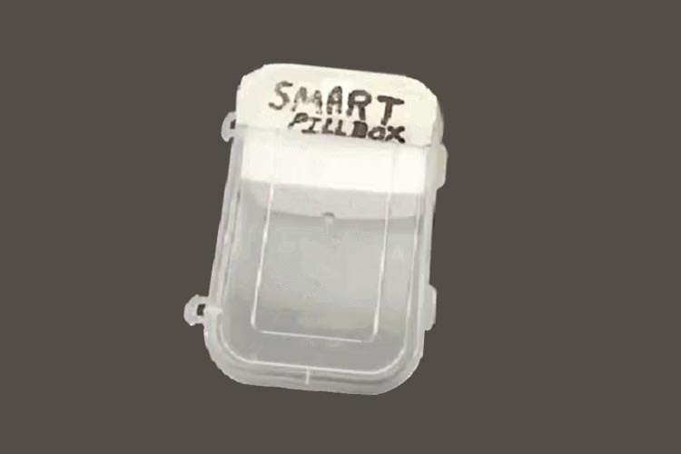
The Smart Pill Box is a smarter way to records how many medicines you are taking at a Day. This smart box contains an ESP-01 Chip, a TCRT5000 module, the AMS1117-3.3v voltage Regulator, and one 3.3v 300mAh Lithium Polymer battery. The TCRT5000 module is used to detect if the lid of the box is closed or not. The ESP-01 is the brain of this smart box which will be connected to the Blynk App over Wi-Fi and send the recorded data. We have previously built Medicine reminder project using Arduino.
Using ESP-01 Wifi Module, we have built many project,
- Build Your Own Compact DIY Smart Switch
- Interface ESP8266-01 Wi-Fi Module with Raspberry Pi Pico using MicroPython
- Alexa controlled Automated ON/OFF Switch for Smart Home
- What is Tasmota and How to use it with ESP-01 to Control Smart Home Devices
- Alexa Controlled Home Automation using Arduino and ESP-01 Wi-Fi Module
Component Requirement for Smart Pill Box
Project Used Hardware
- ESP-01 Chip IC,
- TCRT5000 Module,
- AMS1117-3.3v Regulator,
- 2 x 10uf Electrolytic Capacitor,
- Perf Board.
Project Used Software
- Arduino IDE,
- Blynk Android Application
Project Hardware Software Selection
ESP-01 CHIP: ESP-01 Module is the most widely used because this is the cheaper way to provide Wi-Fi features to the Hardware Applications. It is the best replacement of ESP8266 Development Board. The features of the ESP-01 are similar to the ESP8266 Development board.
TCRT5000 Sensor: The TCRT5000 infrared sensor module features strong drive ability, good waveform, and clear signal. This module can provide high performance for applications such as fax machines, paper shredders, paper testing, and for your projects requiring watt-hour meter pulse data sampling, black and white detection, obstacle detection, and more.
AMS1117-3.3v Voltage Regulator: The AMS1117-3.3v Voltage Regulator is used to give 3.3-volt at the output. I used an SMD version of this regulator. I provided a 3.7-volt power supply at the input and it will provide a 3.3 volt at the output.
Circuit Diagram
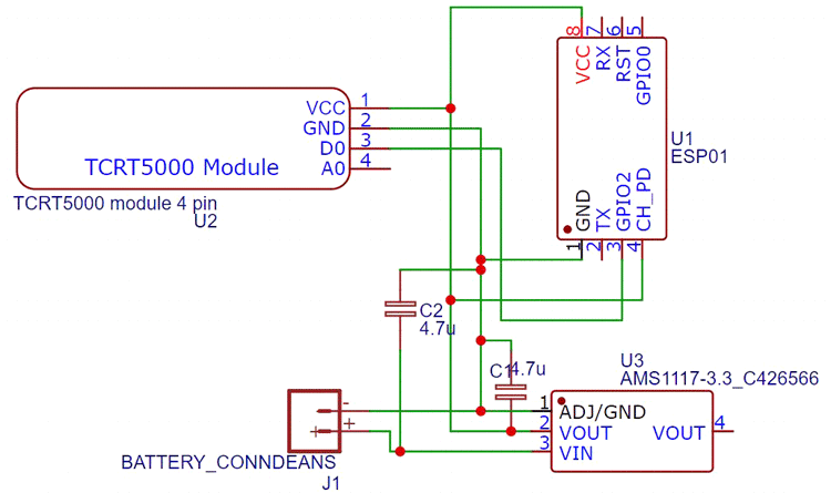
The positive terminal of the 3.7volt battery is connected to the input terminal of the AMS1117-3.3-volt regulator with a 4.7uF capacitor. The output pin of the AMS1117 IC is connected to the VCC pins of the TCRT5000 Module and the ESP-01 Module with a 4.7uF capacitor. The GPIO-2 pin of the ESP-01 is further connected to the D0 pin of the TCRT5000 module. All the Ground pins are connected to each other.
Complete Project Code
#define BLYNK_PRINT Serial
#include <ESP8266WiFi.h>
#include <BlynkSimpleEsp8266.h>
#define irPin 2
WidgetLED led1(V2);// Virtual Pin V2
WidgetLCD lcd(V1);
BlynkTimer timer;
char auth[] = "x-q3D8o-Bu9_dnwXVDH5AQRQhy5FRlod";
// Enter WiFi SSID and Password
char ssid[] = "********";
char pass[] = "********";
int intake=0;
int remaining= 0;
int total = 0;
BLYNK_WRITE(V5)
{  intake=0;
   total = 0;
   total = param.asInt();
remaining = total;
  Serial.println(total);
}
void setup()
{
  Serial.begin(115200);
  delay(10);
  Blynk.begin(auth, ssid, pass);
  pinMode(irPin, INPUT);
  timer.setInterval(300L,sensorvalue);
}
void loop()
{
  Blynk.run();
  timer.run();
}
void sensorvalue(){
  int value = digitalRead(irPin);
  delay(1000);
  if(value == HIGH){
         led1.off();
    intake++;
    remaining = total - intake;
    delay(5000);
  }
  else{
    led1.on();
  }
if(remaining<0){
  Blynk.notify("Medicine box is empty.");
  }else {
    Blynk.virtualWrite(V4,intake);
  Blynk.virtualWrite(V1,remaining);
    }
}


