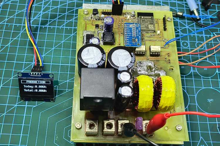
This project is a MPPT solar charge controller based on the ESP32-S3 microcontroller from Espressif. For those unfamiliar with MPPT, it stands for Maximum Power Point Tracking.
MPPT is a technique used to maximize the power output of photovoltaic (PV) panels by adjusting the load on the panel to match the point at which its output power is maximized. This is achieved by monitoring and analyzing the current and voltage output of the PV panel and then adjusting the load accordingly. By implementing MPPT, this project aims to significantly improve the efficiency of solar charging systems and maximize the amount of energy generated.
This project is ongoing, the testing is not completed yet. And so, some features are still missing. For example, the code doesn't yet include the cooling fan and navigation buttons for the screen, although provisions for them have been made on the PCB. These features can be easily added in the future.
MPPT Solar Charge Controller Specifications
- Input: Maximum Open-Circuit Voltage (VOC): 100V
- Output: Maximum Charging Current: 30A and Maximum Battery Bank Voltage: 30V
- MPPT Algorithm: Perturb and Observe
- Conversion Efficiency: Approximately 95% (Not fully tested)
- Topology: Dual Phase Interleaved Buck
- Protections: Input Overvoltage Protection, Output Overvoltage Protection, Over Current Protection, Overtemperature Protection
- Additional Features: Auto Disconnect PV Panel at Night, Auto Disconnect PV Panel on Abnormality, 1.3-inch OLED Display for Real-time Data
Interleaved Buck Converters: Power and Efficiency Enhancement
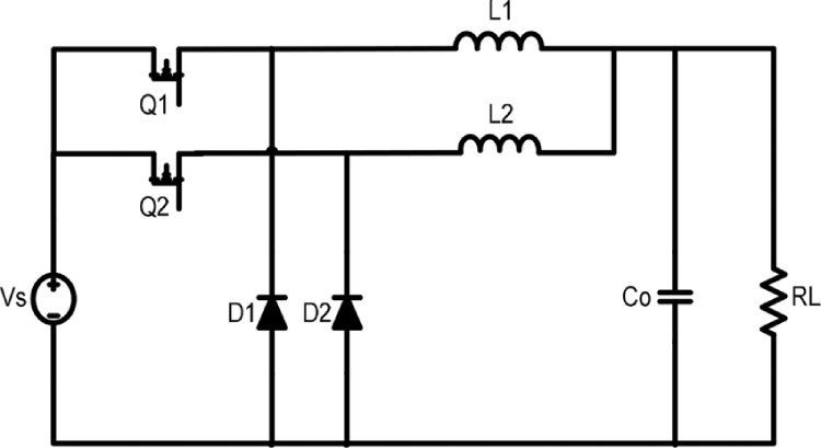
This MPPT controller utilizes a dual-phase interleaved buck topology. This means it uses two identical buck converters connected in parallel, sharing the load and offering several advantages over a single-phase buck converter.
Benefits of Interleaved Buck Converters:
- Reduced Input and Output Ripple: By sharing the load, the interleaved buck converter significantly reduces both input and output current ripple. This translates to cleaner power delivery and less stress on connected components.
- Higher Efficiency: Lower ripple currents lead to lower switching losses, significantly increasing overall conversion efficiency. This means you get more usable power from your solar panels.
- Improved Thermal Performance: By distributing the heat generated across two converters, the interleaved topology prevents excessive heating in any single component, enhancing thermal stability and reliability.
- Increased Current Capacity: Interleaving effectively doubles the current capacity compared to a single-phase buck converter, enabling support for higher charging currents and larger battery banks.
Asynchronous buck converters can be less efficient than synchronous ones. However, using an interleaved buck design allows for improved efficiency in asynchronous converters. Overall, the use of a dual-phase interleaved buck topology in this MPPT controller contributes to its efficiency, performance, and overall reliability.
PWM Generation and Phase Shifting
This MPPT controller utilizes the ESP32's LEDC library to generate the necessary PWM (Pulse Width Modulation) signals for controlling the buck converters. The PWM frequency is set to 39kHz, ensuring efficient power delivery and minimal ripple.
To achieve the required 180-degree phase shift between the two buck converters, the library's "hpoint" parameter is utilized. In this case, a value of 1023 is assigned to the hpoint parameter, resulting in a 180-degree offset between the two PWM signals. This ensures synchronized operation of the interleaved buck converters, maximizing efficiency and minimizing current ripple.
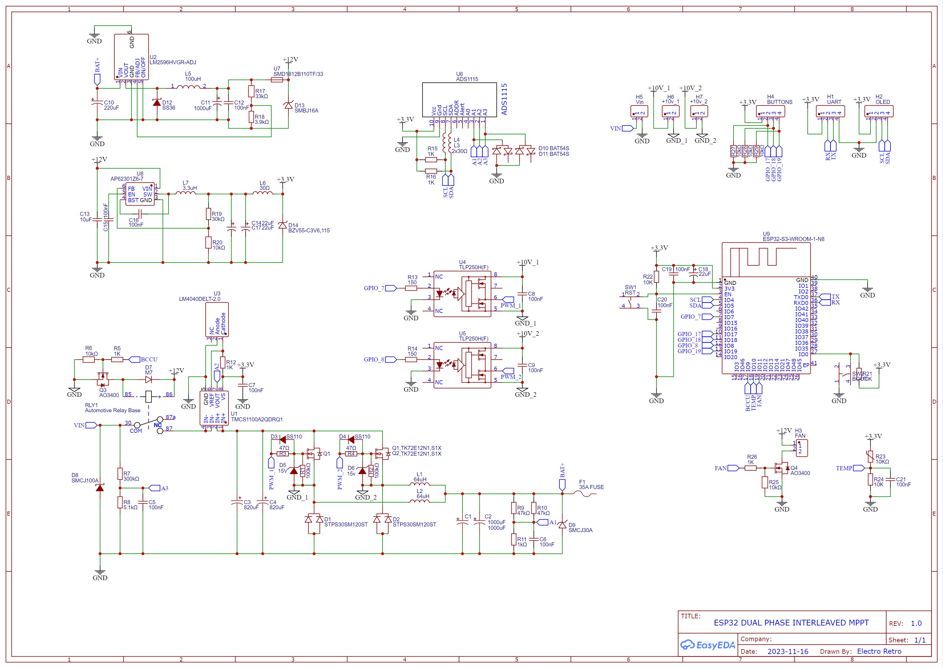
Now let’s take a look at the schematic and components used.
This is the link to easy (oshwlab), you can view and edit the schematic and PCB here and also view the Bill of materials.
Main Switching Buck:
- Q1 and Q2: These are the two main MOSFETs responsible for switching in the buck converter. While the intended MOSFETs for the buck converter are the TK72E12N1 or equivalent, featuring a voltage rating exceeding 100V and ideally boasting low RDS(on) and gate charge, I am currently utilizing STP150N10F7s due to the temporary unavailability of the preferred option.
- D1 and D2: These are high-power Schottky diodes responsible for freewheeling current during the off-cycle. Equivalent options include TST30H120CW C0G, SBR30A120CT, and STPS30SM120ST.
Input and Output Capacitors:
- C1, C2, C3, and C4: These capacitors handle input and output filtering. Low-ESR (Equivalent Series Resistance) capacitors are recommended for optimal performance.
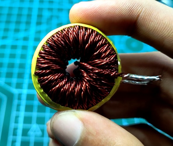
Inductors L1 and L2: These inductors store energy during the on-cycle and release it during the off-cycle, contributing to smooth current flow. The specific core used in this project is the 0077932A7 core sourced from Digikey.
If you're using a different core than the 0077932A7, you can utilize online resources to ensure proper operation. Websites like Pigeonsnest or Angelo Casimiro's (Tech Builder) Excel saturation calculator allow you to verify the saturation current for your chosen core.
Once you've confirmed the core's capabilities, use online calculators like coil32 to determine the number of turns required for your desired inductance value (60uH in this case). For the 60uH inductor, 25SWG five enameled copper wires were twisted together (Litz wire) to minimize the skin effect. Approximately 40 turns were then wound around the core.
Voltage Measurement:
R7, R8, R9, R10, and R11: These resistors form voltage divider circuits responsible for measuring both input and output voltage of the MPPT controller.
Current Measurement with TMCS1100A2(U1) and LM4040DELT-2.0(U3)
This project utilizes the TMCS1100A2 Hall effect current sensor for precise current measurement. The advantage of TMCS1100A2 lies in its dedicated external pin for setting the zero current voltage. This is crucial because traditional Hall effect sensors typically set their zero current voltage at half the supply voltage. For example, a 5V supply would result in a 2.5V zero current voltage, which fluctuates with any variations in the supply voltage.
To address this, the project incorporates the LM4040DELT-2.0 voltage reference IC from STMicroelectronics, obtained from Digikey. This dedicated reference IC provides a stable and accurate voltage to set the TMCS1100A2's zero current voltage precisely to 2.048 volts, ensuring consistent and reliable current measurement regardless of supply voltage fluctuations.
Safety First: Disconnecting PV with an Automotive Relay
This project prioritizes safety by employing a (RLY1) 30A automotive relay to automatically disconnect the photovoltaic (PV) panel under two circumstances:
- Nighttime: When darkness falls, the relay disconnects the PV panel to prevent unnecessary power drain and potential damage from reverse current flow.
- Anomaly Detection: If the system detects any abnormal conditions, such as overvoltage, overcurrent, or MOSFET short, the relay swiftly disconnects the PV panel to safeguard the system and prevent potential harm.
Isolated MOSFET Drive: TLP250H (U4, U5) and Future Plans
The project utilizes the TLP250H isolated MOSFET driver for safe and reliable control of the high-power switching elements. However, an isolated DC-DC power supply is currently absent, which is crucial for asynchronous buck converters. To drive the MOSFETs efficiently, a dedicated isolated DC-DC power supply is necessary to provide the voltage required across the source and gate terminals. Unfortunately, due to time constraints, the project currently lacks this component.
While two separate 10V external power supplies are temporarily employed to power the TLP250H, this is not an ideal solution for long-term operation. Plans to design and implement a dedicated isolated DC-DC converter are underway, and updates will be provided once the development is complete.
Precise Measurement with the ADS1115 ADC: Buyer Beware!
This project relies on the accurate voltage and current measurements provided by the ADS1115 analog-to-digital converter (ADC). However, when purchasing an ADS1115 breakout board, it's crucial to choose a trusted source like DIGIKEY. Unfortunately, the initial board acquired for this project contained an ADS1015 instead of the intended ADS1115. This resulted in inaccurate readings and required manual replacement with the genuine ADS1115 to ensure reliable measurements.
Therefore, it's important to emphasize the importance of sourcing components from reputable vendors like DIGIKEY to guarantee their authenticity and ensure optimal performance of your project.
The MPPT controller utilizes two dedicated voltage regulators for efficient power distribution:
- LM2596HVGR-ADJ (U2): This regulator provides a stable 12V output, powering the cooling fan and relay.
- AP62301Z6-7 (U8): This regulator supplies a precise 3.3V output, powering the ESP32 microcontroller, ADS1115 ADC, and TMCS1100 current sensor.
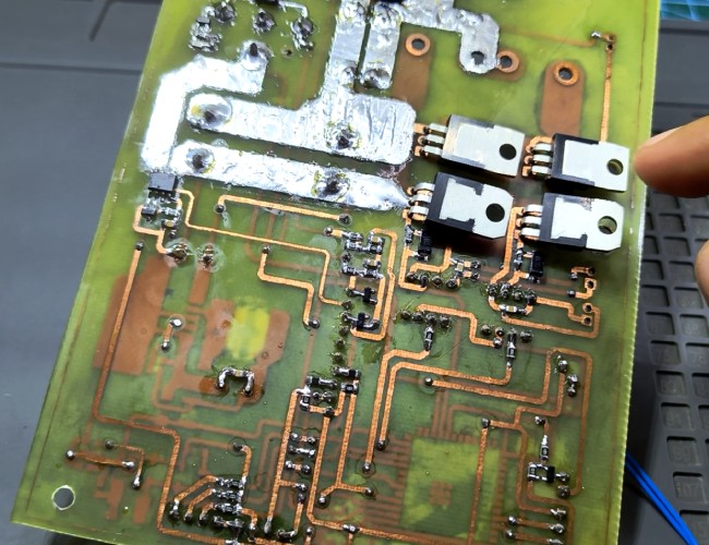
After completing the PCB design, I began fabricating the circuit board using a double-sided copper clad board.
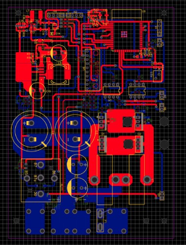
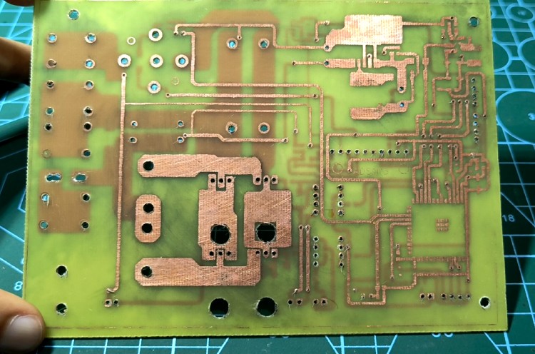
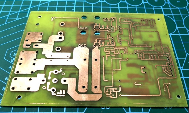
After assembling the SMD components and vias, I applied conformal coating for protection and then inserted the through-hole components one by one
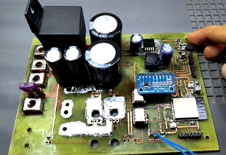
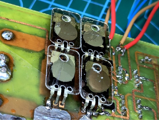
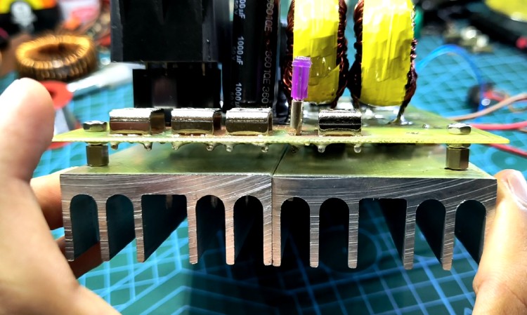
To properly mount the MOSFETs on the heatsink:
- Apply solder paste: Apply thermal paste to both the MOSFET tab and the heatsink contact area.
- Mica insulation: Place a mica insulator sheet between the MOSFET tab and the heatsink.
- Insulated washer: Use an insulated washer on the screw that goes through the MOSFET tab. This will ensure electrical isolation from the heatsink.
These steps are crucial for preventing electrical short circuits and ensuring optimal heat dissipation from the MOSFETs.
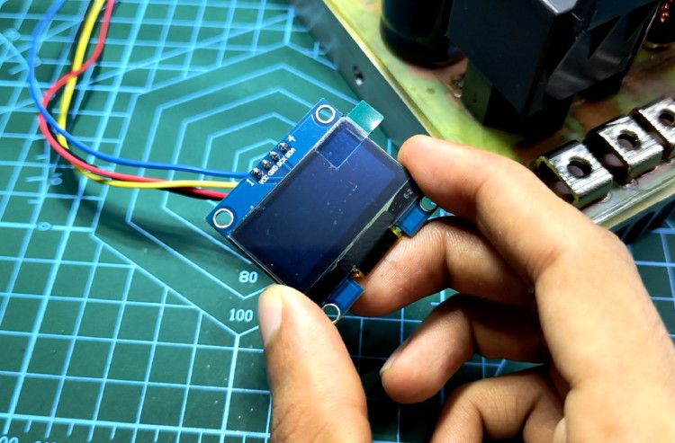
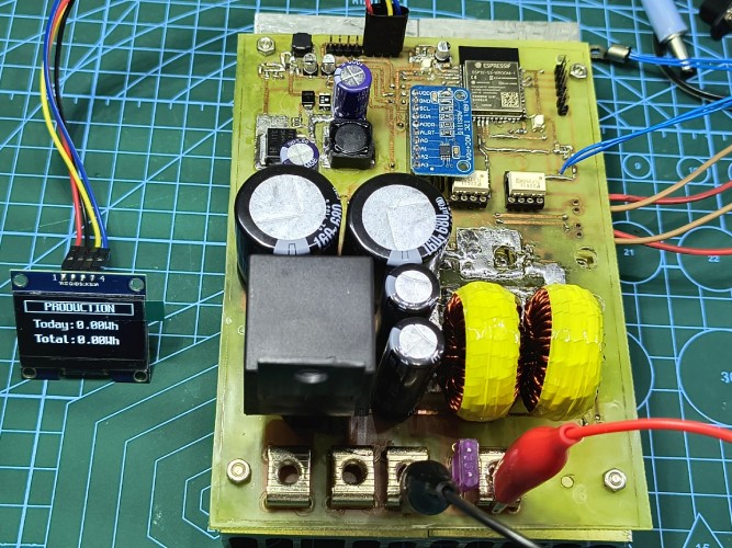
After connecting the OLED display to the MPPT controller and the USB-to-TTL chip to a PC, I programmed the ESP32 with parameters for a 12V lead-acid battery. Once programmed, a 12V 35Ah battery was connected to the designated terminal. It's crucial to connect the battery first and avoid disconnecting it during operation. Asynchronous buck converters require a load on the output to regulate the voltage Following the battery connection, I configured my power supply to deliver 30V and 5A, simulating the output of a solar panel.
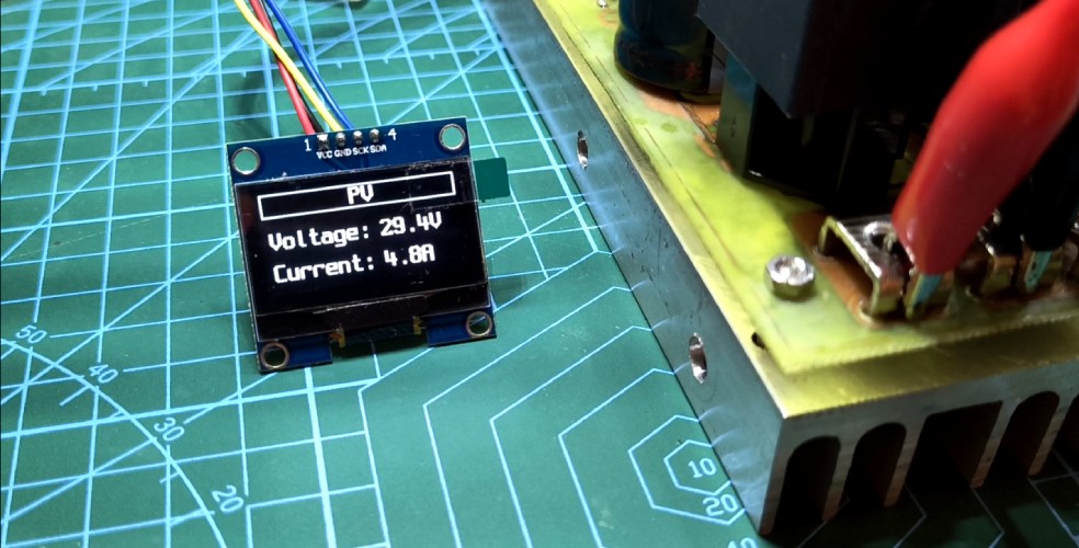
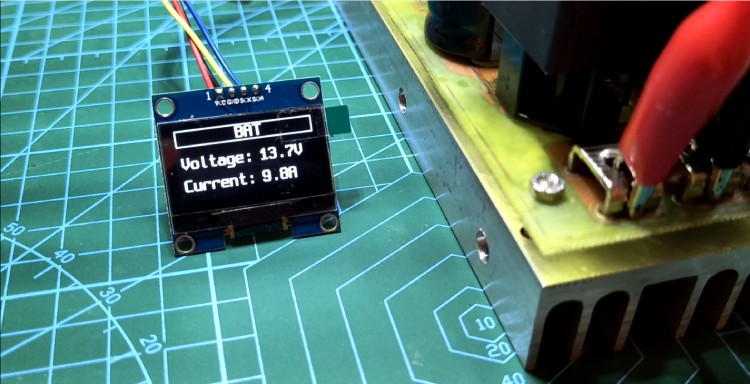
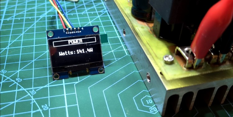
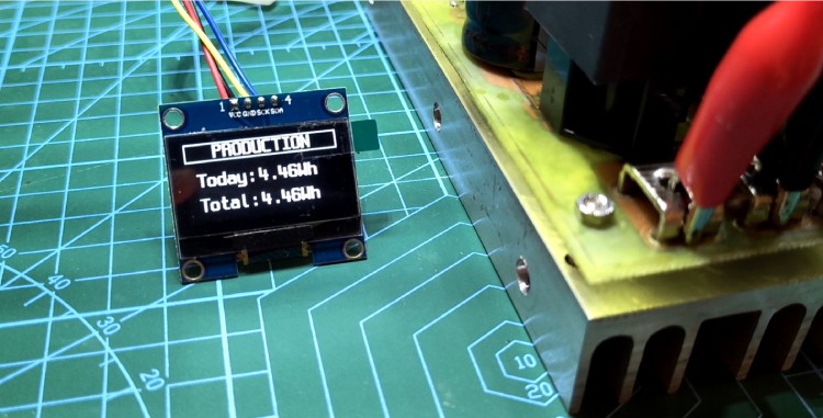
The MPPT controller will continuously monitor for abnormalities. If no anomalies are detected, Within the 10-second delay the relay will engage, activating the MPPT and initiating the charging process. The OLED display will then provide real-time information, including Input Voltage, Output Voltage, Input Current, Input Power, Production Today: Tracks the cumulative energy generated by the MPPT controller for the current day, Production Total: Shows the total energy generated by the MPPT controller since its initial operation.
If an anomaly is detected during operation, the MPPT controller will take appropriate action, such as disconnecting the PV panel or adjusting the charging parameters, to protect the system and ensure safe operation. And finally, I would like to express my sincere gratitude to Circuit Digest and Digi-Key for providing this valuable opportunity. Additionally, I extend my deepest appreciation to Angelo Casimiro for his meticulous and insightful documentation of his MPPT project. His work has served as a tremendous source of inspiration and guidance throughout my own project.
Complete Project Code
//ESP32 MPPT Firmware
#include "driver/ledc.h"        //- ledc.h
#include "esp_timer.h"          //- High Resolution Timer (ESP Timer)
#include <Adafruit_ADS1X15.h>   //- ADS1115/ADS1015 ADC Library (By: Adafruit)
#include "MovingAverage.h"      //- MovingAverage Filter By Ian Carey
#include <U8g2lib.h>            //- U8g2lib Library For Display
#include <Wire.h>               //- Library Requires For IIC Communication
ledc_timer_config_t ledc_timer;
ledc_channel_config_t ledc_channel;
ledc_timer_config_t ledc_timer_2;
ledc_channel_config_t ledc_channel_2;
Adafruit_ADS1115 ads;
// The complete list is available here: https://github.com/olikraus/u8g2/wiki/u8g2setupcpp
// Please update the pin numbers according to your setup. Use U8X8_PIN_NONE if the reset pin is not connected
U8G2_SH1106_128X64_NONAME_F_HW_I2C u8g2(U8G2_R0, /* reset=*/ U8X8_PIN_NONE);
#define SDA             5   //SYSTEM PARAMETER - Serial Data
#define SCL             4   //SYSTEM PARAMETER - Serial Clock
#define PWM_PIN         7   //SYSTEM PARAMETER - Choose any available PWM-capable pin on your ESP32
#define PWM_PIN_2       8   //SYSTEM PARAMETER - Choose any available PWM-capable pin on your ESP32
#define BCCU            9   //SYSTEM PARAMETER - BACKFLOW CURRENT CONTROL UNIT Relay pin.
#define TempSensor      10  //SYSTEM PARAMETER - Temperature Sensor GPIO Pin
MovingAverage filter1(20);  // Output Voltage Filter Value
MovingAverage filter2(50);  // Input Current Filter Value
MovingAverage filter3(20);  // Input Voltage Filter Value
float
PV_VoltageMax        = 90.000,    //  USER PARAMETER - Maximum PV Voltage (Input V)
PV_VoltageMin        = 16.000,    //  USER PARAMETER - Minimum PV Voltage (Input V)
PV_CurrentMax        = 20.000,    //  USER PARAMETER - Maximum PV Current (Input A)
BatteryVoltageMax    = 14.000,    //  USER PARAMETER - Maximum Battery Charging Voltage (Output V)
BatteryCurrentMax    = 30.000,    //  USER PARAMETER - Maximum Battery Current (Output A)
temperatureMax       = 75;        //  USER PARAMETER - Overtemperature, System Shudown When Exceeded (deg C)
int
avgCountTS             = 500,     //  CALIB PARAMETER - Temperature Sensor Average Sampling Count
OLED_Update_micros     = 2000000, //  CALIB PARAMETER - Time interval refresh rate for OLED display (us), Default = 2s.
OLED_Toggle_micros     = 5000000, //  CALIB PARAMETER - Time interval for showing next screen on OLED Display
ReconnectTime_micros   = 10000000,//  CALIB PARAMETER - Time delay for reconnecting PV (us), Default = 10s.
RoutineInterval_micros = 250000;  //  CALIB PARAMETER - Time Interval Refresh Rate For Routine Functions (us)
float
inVoltageDivRatio    = 59.808,    //  CALIB PARAMETER - Input voltage divider sensor ratio (change this value to calibrate voltage sensor)
outVoltageDivRatio   = 24.4970,   //  CALIB PARAMETER - Output voltage divider sensor ratio (change this value to calibrate voltage sensor)
ntcResistance        = 10000.00,   //  CALIB PARAMETER - NTC temp sensor's resistance.
efficiencyRate       = 0.9500,    //  CALIB PARAMETER - Theroretical Buck Efficiency (% decimal)
currentMidPoint      = 2.040,     //  CALIB PARAMETER - Current Sensor Midpoint (V)
currentSensV         = 0.1000,    //  CALIB PARAMETER - Current Sensor Sensitivity (mV/A)
voltageDropout       = 1.0000,    //  CALIB PARAMETER - Buck regulator's dropout voltage
voltageBatteryThresh = 1.5000,    //  CALIB PARAMETER
voltageBatteryMin    = 8.000;     //  CALIB PARAMETER - Minimum Battery voltage
bool
BNC                  = 0,         // SYSTEM PARAMETER - Battery not connected
IUV                  = 0,         // SYSTEM PARAMETER - Input under voltage flag
IOV                  = 0,         // SYSTEM PARAMETER - Input over voltage flag
IOC                  = 0,         // SYSTEM PARAMETER - Input over current flag
OOV                  = 0,         // SYSTEM PARAMETER - Output over voltage flag
OTE                  = 0,         // SYSTEM PARAMETER - Over temperature flag
Buck_Enable          = 0;         // SYSTEM PARAMETER - Buck Enable Status
int
avgStoreTS           = 0,         // SYSTEM PARAMETER - Temperature Sensor uses non invasive averaging, this is used an accumulator for mean averaging
temperature          = 0,         // SYSTEM PARAMETER - Temperature in celsius
sampleStoreTS        = 0,         // SYSTEM PARAMETER - TS AVG nth Sample
screen               = 0;         // SYSTEM PARAMETER - Used for displaying parameters on OLED
float
dutycycle            = 0.0000,    // SYSTEM PARAMETER - PWM Dutycycle
VSI                  = 0.0000,    // SYSTEM PARAMETER - Raw input voltage sensor ADC voltage
VSO                  = 0.0000,    // SYSTEM PARAMETER - Raw output voltage sensor ADC voltage
CSI                  = 0.0000,    // SYSTEM PARAMETER - Raw current sensor ADC voltage
TS                   = 0.0000,    // SYSTEM PARAMETER - Raw temperature sensor ADC value
TSlog                = 0.0000,    // SYSTEM PARAMETER - Part of NTC thermistor thermal sensing code
voltageInput         = 0.0000,    // SYSTEM PARAMETER - Input voltage (solar voltage)
voltageInputPrev     = 0.0000,    // SYSTEM PARAMETER - Previously stored input voltage variable for MPPT algorithm
voltageOutput        = 0.0000,    // SYSTEM PARAMETER - Output voltage (battery voltage)
currentInput         = 0.0000,    // SYSTEM PARAMETER - Input current (solar current)
currentInputPrev     = 0.0000,    // SYSTEM PARAMETER - Previously stored input current variable for MPPT algorithm
currentOutput        = 0.0000,    // SYSTEM PARAMETER - Output current (battery or charing current in Amperes)
powerInput           = 0.0000,    // SYSTEM PARAMETER - Input power (solar power) in Watts
powerInputPrev       = 0.0000,    // SYSTEM PARAMETER - Previously stored input power variable for MPPT algorithm (Watts)
DeltaV               = 0.0000,    // SYSTEM PARAMETER -
DeltaI               = 0.0000,    // SYSTEM PARAMETER -
DeltaP               = 0.0000,    // SYSTEM PARAMETER -
DeltaD               = 0.0000,    // SYSTEM PARAMETER -
daysRunning          = 0.0000,    // SYSTEM PARAMETER - Stores the total number of days the MPPT device has been running since last powered
Hours                = 0.0000,    // SYSTEM PARAMETER - Used for reseting daily production
ProductionTodayWh    = 0.0000,    // SYSTEM PARAMETER - Stores the daily production in Wh
ProductionTodaykWh   = 0.0000,    // SYSTEM PARAMETER - Stores the daily production in kWh
Wh                   = 0.0000,    // SYSTEM PARAMETER - Stores the accumulated energy harvested (Watt-Hours)
kWh                  = 0.0000,    // SYSTEM PARAMETER - Stores the accumulated energy harvested (Kiliowatt-Hours)
MWh                  = 0.0000,    // SYSTEM PARAMETER - Stores the accumulated energy harvested (Megawatt-Hours)
loopTime             = 0.0000;    // SYSTEM PARAMETER -
int64_t
currentOLED_micros       = 0,     // SYSTEM PARAMETER -
currentReconnect_micros  = 0,     // SYSTEM PARAMETER -
currentRoutine_micros    = 0,     // SYSTEM PARAMETER -
prevOLED_micros          = 0,     // SYSTEM PARAMETER -
prevOLED_Toggle_micros   = 0,     // SYSTEM PARAMETER -
prevReconnect_micros     = 0,     // SYSTEM PARAMETER -
prevRoutine_micros       = 0,     // SYSTEM PARAMETER -
prevHour_micros          = 0,     // SYSTEM PARAMETER - Used for daily kWh reset counter
timeOn                   = 0,     // SYSTEM PARAMETER -
loopTimeStart            = 0,     // SYSTEM PARAMETER - Used for the loop cycle stop watch, records the loop start time
loopTimeEnd              = 0;     // SYSTEM PARAMETER - Used for the loop cycle stop watch, records the loop end time
void setup() {
  //SERIAL INITIALIZATION
  Serial.begin(500000);
  //GPIO PIN INITIALIZATION
  pinMode(BCCU, OUTPUT);
  pinMode(TS,INPUT);
  ads.setGain(GAIN_TWO);                 // 2x gain   +/- 2.048V  1 bit = 1mV      0.0625mV
  ads.setDataRate(RATE_ADS1115_860SPS);  // ADS1115 Sampling rate
  Wire.begin(SDA, SCL);                  // I2C PINS INITIALIZATION
  Wire.setClock(400000);                 // Set I2C frequency to 400khz
  ads.begin();                           // ADC INITIALIZATION
  ledc_timer.bit_num = LEDC_TIMER_11_BIT;       // resolution of PWM duty
  ledc_timer.freq_hz = 39000;                   // frequency of PWM signal
  ledc_timer.speed_mode = LEDC_LOW_SPEED_MODE;  // timer mode
  ledc_timer.timer_num = LEDC_TIMER_0;          // timer index
  ledc_timer_config(&ledc_timer);
  ledc_channel.channel = LEDC_CHANNEL_0;
  ledc_channel.duty = 0;
  ledc_channel.gpio_num = PWM_PIN;
  ledc_channel.speed_mode = LEDC_LOW_SPEED_MODE;
  ledc_channel.timer_sel = LEDC_TIMER_0;
  ledc_channel_config(&ledc_channel);
  ledc_timer_2.bit_num = LEDC_TIMER_11_BIT;       // resolution of PWM duty
  ledc_timer_2.freq_hz = 39000;                   // frequency of PWM signal
  ledc_timer_2.speed_mode = LEDC_LOW_SPEED_MODE;  // timer mode
  ledc_timer_2.timer_num = LEDC_TIMER_0;          // timer index
  ledc_timer_config(&ledc_timer_2);
  ledc_channel_2.channel = LEDC_CHANNEL_2;
  ledc_channel_2.duty = 0;
  ledc_channel_2.gpio_num = PWM_PIN_2;
  ledc_channel_2.speed_mode = LEDC_LOW_SPEED_MODE;
  ledc_channel_2.timer_sel = LEDC_TIMER_0;
  ledc_channel_2.hpoint = 1023;                   // 180 degree phase shift
  u8g2.begin();   //OLED INITIALIZATION
  u8g2.clearBuffer();
  u8g2.setFont(u8g2_font_spleen8x16_mf);
  u8g2.drawStr(50, 30, "MPPT ");
  u8g2.drawStr(15, 45, "FIRMWARE-V1.0");
  u8g2.sendBuffer();
  delay(2500);
}
void loop() {
  Read_Sensors();        //TAB#2 - Sensor data measurement and computation
  Device_Protection();   //TAB#3 - Fault detection algorithm
  Charging_Algorithm();  //TAB#4 - Battery Charging Algorithm
  OLED_Menu();           //TAB#5 - OLED Menu
  //////////// LOOP TIME STOPWATCH ////////////
  loopTimeStart = esp_timer_get_time();                             //Record Start Time
  loopTime = (loopTimeStart - loopTimeEnd) / 1000.000;  //Compute Loop Cycle Speed (mS)
  loopTimeEnd = esp_timer_get_time();                               //Record End Time
  //Serial.print(" LoopT:"); Serial.print(loopTime,3);Serial.println("ms");
  Serial.print(voltageInput);
  Serial.print("V ");
  Serial.print(currentInput);
  Serial.print("A ");
  Serial.print(voltageOutput);
  Serial.print("V ");
  Serial.print(currentOutput);
  Serial.print("A ");
  Serial.print(loopTime);
  Serial.println("ms ");
}
//OLED Menu
void OLED_Menu() {
  currentOLED_micros = esp_timer_get_time();
  if (currentOLED_micros - prevOLED_micros >= OLED_Update_micros ) {
   u8g2.clearBuffer();                  // clear the internal memory
   if(screen == 0){screen_1();}
   else if(screen == 1){screen_2();}
   else if(screen == 2){screen_3();}
   else if(screen == 3){screen_4();}
   u8g2.sendBuffer();                     // transfer internal memory to the display
   prevOLED_micros = currentOLED_micros;
  }
  //Toggle screen
  if (currentOLED_micros - prevOLED_Toggle_micros >= OLED_Toggle_micros) {
   screen++;
   if(screen > 3){screen = 0;}
   prevOLED_Toggle_micros = currentOLED_micros;
  }
}
void screen_1(){ //Screen No:1, Print PV(solar) Voltage and Current
   u8g2.setFont(u8g2_font_spleen8x16_mf);
  u8g2.setCursor(58, 12); u8g2.print("PV");
  u8g2.drawFrame(2, 0, 124, 15);
  u8g2.setCursor(5, 35);  u8g2.print("Voltage:");
  u8g2.setCursor(75, 35); u8g2.print(voltageInput,1);  u8g2.println("V");
  u8g2.setCursor(5, 55);  u8g2.print("Current:");
  u8g2.setCursor(75, 55); u8g2.print(currentInput,1);  u8g2.println("A");
}
void screen_2(){ //Screen No:2, Print Battery Voltage and Current
   u8g2.setFont(u8g2_font_spleen8x16_mf);
  u8g2.setCursor(56, 12); u8g2.print("BAT");
  u8g2.drawFrame(2, 0, 124, 15);
  u8g2.setCursor(5, 35);  u8g2.print("Voltage:");
  u8g2.setCursor(75, 35); u8g2.print(voltageOutput,1);  u8g2.println("V");
  u8g2.setCursor(5, 55);  u8g2.print("Current:");
  u8g2.setCursor(75, 55); u8g2.print(currentOutput,1);  u8g2.println("A");
}
void screen_3(){ //Screen No:3, Print input power
  u8g2.setFont(u8g2_font_spleen8x16_mf);
  u8g2.setCursor(46, 12); u8g2.print("POWER");
  u8g2.drawFrame(2, 0, 124, 15);
  u8g2.setCursor(15, 42); u8g2.print("Watts:");
  u8g2.setCursor(65, 42); u8g2.print(powerInput,1);  u8g2.println("W");
}
void screen_4(){ //Screen No:4, Print daily and total production
  u8g2.setFont(u8g2_font_spleen8x16_mf);
  u8g2.setCursor(25, 12); u8g2.print("PRODUCTION");
  u8g2.drawFrame(2, 0, 124, 15);
  u8g2.setCursor(10, 35); u8g2.print("Today:");
  u8g2.setCursor(60, 35);
  if(ProductionTodayWh<10){u8g2.print(ProductionTodayWh,2);         u8g2.println("Wh");}
  else if(ProductionTodayWh<100){u8g2.print(ProductionTodayWh,1);    u8g2.println("Wh");}
  else if(ProductionTodayWh<10000){u8g2.print(ProductionTodaykWh,2);  u8g2.println("kWh");}
  else if(ProductionTodayWh<100000){u8g2.print(ProductionTodaykWh,1);  u8g2.println("kWh");}
  u8g2.setCursor(10, 55); u8g2.print("Total:");
  u8g2.setCursor(60, 55);
  if(Wh<10){u8g2.print(Wh,2);         u8g2.println("Wh");}
  else if(Wh<100){u8g2.print(Wh,1);    u8g2.println("Wh");}
  else if(Wh<10000){u8g2.print(kWh,2);  u8g2.println("kWh");}
  else if(Wh<100000){u8g2.print(kWh,1);  u8g2.println("kWh");}
  else if(Wh<1000000){u8g2.print(kWh,0);  u8g2.println("kWh");}
  else if(Wh<10000000){u8g2.print(MWh,1);  u8g2.println("MWh");}
  else if(Wh<100000000){u8g2.print(MWh,0);  u8g2.println("MWh");}
  else if(Wh<1000000000){u8g2.print(MWh,0);  u8g2.println("MWh");}
}
//Charging algorithum
void Charging_Algorithm() {
  dutycycle = constrain(dutycycle, 0, 2047); //constrain dutycycle
   if(Buck_Enable == 1){
    if(voltageOutput>BatteryVoltageMax)            {dutycycle-= 1;}            //  Voltage Is Above → Decrease Duty Cycle
    else if(currentOutput > BatteryCurrentMax)     {dutycycle-= 0.1;}          //  Current Is Above → Decrease Duty Cycle
     else{                                                                     //    MPPT ALGORITHM
          if(DeltaP > 0.0000 && DeltaV > 0.0000)             {dutycycle-=1;}   //  ↑P ↑V ; →MPP  //D--
          else if(DeltaP > 0.0000 && DeltaV < 0.0000)        {dutycycle+=1;}   //  ↑P ↓V ; MPP←  //D++
          else if(DeltaP < 0.0000 && DeltaV > 0.0000)        {dutycycle+=1;}   //  ↓P ↑V ; MPP→  //D++
          else if(DeltaP < 0.0000 && DeltaV < 0.0000)        {dutycycle-=1;}   //  ↓P ↓V ; ←MPP  //D--
          else if(voltageOutput<BatteryVoltageMax) {dutycycle+=1;}             //  MP MV ; MPP Reached -
          powerInputPrev   = powerInput;                                       //  Store Previous Recorded Power
          voltageInputPrev = voltageInput;                                     //  Store Previous Recorded Voltage
        }
   }
  ledcWrite(0, dutycycle); //Write PWM duty cycle to channel_0
  ledcWrite(2, dutycycle); //Write PWM duty cycle to channel_2
}
//device protection
void backflowControl() {
  unsigned long currentReconnect_micros = esp_timer_get_time();
  //If any anomaly happens disconnect the buck immediately and if everything is normal reconnect buck after some delay
  if (BNC == 1 || IUV == 1 || IOV == 1 || IOC == 1 || OOV == 1 || OTE == 1) {
    buck_Disable();
    prevReconnect_micros = currentReconnect_micros;
  } else if (voltageInput >= PV_VoltageMin && currentReconnect_micros - prevReconnect_micros >= ReconnectTime_micros) {
    buck_Enable();
  }
}
void buck_Enable() {     //Enable BUCK
  digitalWrite(BCCU, 1);
  Buck_Enable = 1;
}
void buck_Disable() {    //Disable BUCK
  digitalWrite(BCCU, 0);
  Buck_Enable   = 0;
  dutycycle     = 0;
  currentInput  = 0;
  currentOutput = 0;
  powerInput    = 0;
}
void Device_Protection() {
  if(voltageOutput < voltageBatteryMin)                       {BNC = 1;} else{BNC = 0;} //BNC - Battery Not Connected
  if(voltageInput < voltageOutput + voltageDropout)           {IUV = 1;} else{IUV = 0;} //IUV - Input Under Voltage
  if(voltageInput > PV_VoltageMax)                            {IOV = 1;} else{IOV = 0;} //IOV - Input Over Voltage
  if(currentInput > PV_CurrentMax)                            {IOC = 1;} else{IOC = 0;} //IOC - Input Over Current
  if(voltageOutput > BatteryVoltageMax + voltageBatteryThresh){OOV = 1;} else{OOV = 0;} //OOV - Output Over Voltage
  if(temperature>temperatureMax)                              {OTE = 1;} else{OTE = 0;} //OTE - OVERTEMPERATURE: System overheat detected
  backflowControl();
}
//Read Sesnors
void Read_Sensors() {
    /////////// TEMPERATURE SENSOR /////////////
  if(sampleStoreTS<=avgCountTS){                               //TEMPERATURE SENSOR - Lite Averaging
    TS = TS + analogRead(TempSensor);
    sampleStoreTS++;
  }
  else{
    TS = TS/sampleStoreTS;
    TSlog = log(ntcResistance*(4095.00/TS-1.00));
    temperature = (1.0/(1.009249522e-03+2.378405444e-04*TSlog+2.019202697e-07*TSlog*TSlog*TSlog))-273.15;
    sampleStoreTS = 0;
    TS = 0;
  }
  //FILTERING
  VSI = filter3.addSample(ads.computeVolts(ads.readADC_SingleEnded(3)));
  VSO = filter1.addSample(ads.computeVolts(ads.readADC_SingleEnded(1)));
  CSI = filter2.addSample(ads.computeVolts(ads.readADC_SingleEnded(2)));
  //VOLTAGE SENSOR
  voltageInput = VSI * inVoltageDivRatio;
  voltageOutput = VSO * outVoltageDivRatio;
  //CURRENT SENSOR
  currentInput = ((CSI - currentMidPoint) * -1) / currentSensV;
  if (currentInput < 0) { currentInput = 0.0000; }
  if (voltageOutput <= 0) { currentOutput = 0.0000; }
  else {currentOutput = (voltageInput*currentInput)/voltageOutput*efficiencyRate;}
  //POWER COMPUTATION - Through computation
  powerInput = voltageInput * currentInput;
  DeltaV = voltageInput - voltageInputPrev;
  DeltaI = currentInput - currentInputPrev;
  DeltaP = powerInput - powerInputPrev;
  //TIME DEPENDENT SENSOR DATA COMPUTATION
  currentRoutine_micros = esp_timer_get_time();
  if(currentRoutine_micros - prevRoutine_micros >= RoutineInterval_micros){   //Run routine every millisRoutineInterval (ms)
    prevRoutine_micros = currentRoutine_micros;                               //Store previous time
    if(Buck_Enable == 1){
      Wh = Wh+(powerInput/(3600.000*(1000000.000/RoutineInterval_micros)));   //Accumulate and compute energy harvested (3600s*(1000/interval))
      ProductionTodayWh = ProductionTodayWh+(powerInput/(3600.000*(1000000.000/RoutineInterval_micros)));
    }
    kWh = Wh/1000.000;
    MWh = Wh/1000000.000;
    ProductionTodaykWh = ProductionTodayWh/1000.000;
    daysRunning = timeOn/(86400.000*(1000000.000/RoutineInterval_micros));    //Compute for days running (86400s*(1000/interval))
    timeOn++;                                                                 //Increment time counter
  }
  //Reset production daily. If there is no solar presense for more than 10 hours, Reset production.
  if(IUV == 1){
    Hours = ((currentRoutine_micros - prevHour_micros) / 3600000000.000);
  }
  if(IUV == 0){
    prevHour_micros = currentRoutine_micros;
    if(Hours >= 10){ProductionTodayWh = 0; Hours = 0;}
  }
}
