Walking safely and confidently can be a challenging task for visually impaired individuals, but with the help of technology, we can make it easier for them. This DIY Blind Stick is an innovative yet simple solution that is designed to help users detect obstacles in their path. Using an Arduino Nano, ultrasonic sensor, and buzzer, it can sense objects in their way and provide an instant audible alert to them. So they can navigate independently.
The best part of this blind stick Arduino project is that it’s easy to build, affordable and products similar to this, like Torchit has even been featured on shark tank. The ultrasonic sensor acts like a third eye, helping to calculate the distance to objects. The Arduino keeps on processing the data from the ultrasonic sensor, and it quickly triggers the Audio alert when it detects something nearby.
Here, you’ll learn how to interface the ultrasonic sensor with Arduino and how to write code that responds to nearby obstacles instantly with zero latency. This is crucial for the navigation of people with vision challenges. Let’s start building this Arduino blind stick and make life safer for those who need it! You can also check out our other Arduino Projects if you need more ideas for building projects using Arduino.
Table of Contents
How does a Blind Stick using Arduino Work?
This Arduino walking stick is designed to help visually impaired people move around safely and independently. It works by detecting obstacles and warning the people through a buzzer beep alert. Here, I also added an LED alert to help people with partial vision loss. Ok, let’s see how this smart stick works step by step:
Detecting Obstacles
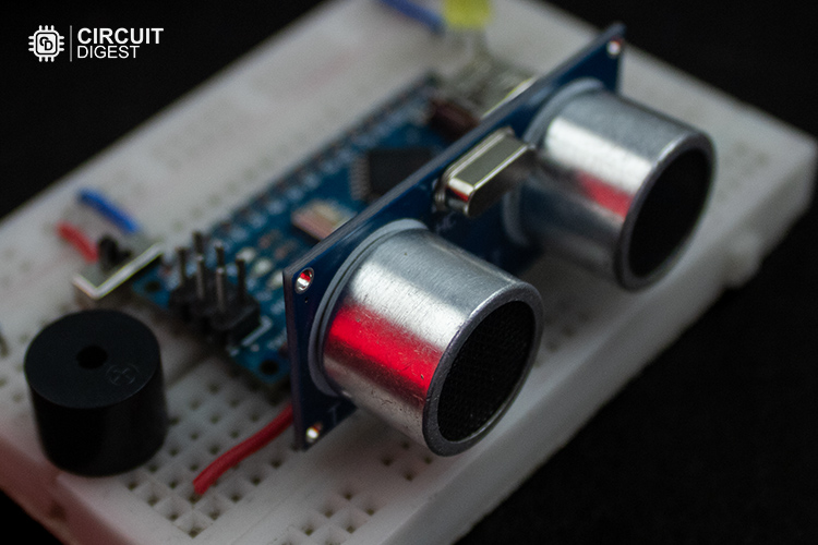
The heart of this stick is the ultrasonic sensor, which acts like the stick’s "eyes". It sends out ultrasonic waves (whenever the TRIG pin of the sensor gets triggered by Arduino) that bounce off objects and return to the sensor. Later, it measures the time it takes for the waves to come back and finally send out that measured time as a (timing pulse signal) to Arduino via ECHO pin.
If you are new in handling the Ultrasonic Sensor, feel free to check out this Arduino Ultrasonic sensor tutorial for a detailed explanation.
Data Reception and Distance Calculation
The Arduino acts as the brain of the walking stick. It takes the timing pulse signal from the ECHO pin of the Ultrasonic sensor for calculating the time taken by the wave to hit and bounce back from the object.
After knowing the time taken in microseconds, the distance in centimeters is calculated using the formula below.
{Distance = (Time taken by the signal to Hit and bounce back / 2) / 29.1}
For example, let’s say the signal takes 500 microseconds to hit and bounce back, then
Distance = (500 / 2) / 29.1 => 8.59 cm
The object is approximately 8.59 cm away from the sensor.
Audio Based Obstacle Detection and Alerts Using Arduino
When an obstacle is detected within the safety range(50 cm), the Arduino triggers two alert systems:
Buzzer: It makes a sound to warn the user of the nearby object. The closer the object, the faster the buzzer can beep to give the sense that the object is nearing them.
LED Light: A light flashes to provide a visual alert for those with partial vision. It also increase it flash rate when the object is nearing them.
That’s all about the working of our Arduino Blind Man walking stick. Let's know what are the things do we need to build it.
Components Required for The Smart Blind Stick
Here is the simple list of components, which is needed to build a Blind Stick project using Arduino.
Arduino Nano
HC-SR04 Ultrasonic Sensor
5V Active Buzzer
Light-Emitting Diode
Current Limiting Resistor
9V Battery
Slidder switch / on-off switch
Breadboard
Connecting wires
PVC Pipe
Up next, we’ll take a look at the block diagram of this Smart Walking Stick using Arduino, giving a clear overview of how its components work together.
Block Diagram Representation of Arduino-Based Blind Stick
The following block diagram shows the topology of a smart blind stick using Arduino Nano, showing how each component is related to others.
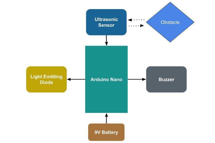
I hope you understand the complete system overview. Let’s start to design the circuit diagram for our Smart Blind Stick.
Smart Blind Stick using Arduino Circuit Diagram
The below circuit diagram shows the complete hardware wiring setup of the Arduino-based Smart Walking Stick for the Blind people, detailing how the Arduino Nano, Ultrasonic sensors, Buzzer, and Led lights are secured together to form a functional blind stick hardware unit.

For the power supply, I decided to use a 9V battery, but in reality, it better to use the rechargeable 9V battery. Here, you can find that i am powering the ultrasonic sensor directly from the Arduino GPIO pins to avoid connection complexity, especially in Smaller breadboards.
Note that the ultrasonic sensor generally consumes only 15mA, which is enough to power it directly from Arduino GPIO.
Hardware Connections of Obstacle Detection Stick for the Blind
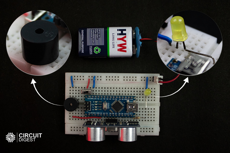
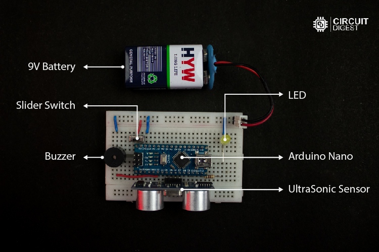
Below is the actual hardware setup used to build our ultrasonic blind walking stick using arduino, utilizing Arduino and Ultrasonic sensors. This setup is constructed based on the previously discussed circuit diagram, demonstrating the practical assembly of the system.
That’s all about the hardware wiring connection part, it’s time to bring back life to our actual hardware by coding software for it. Let's move on to the coding part.
Blind Stick using Arduino Code
The complete Arduino Code to build a smart blind stick using Arduino nano and an Ultrasonic sensor is given at the bottom of this page. This is the code for the Smart blind stick using Arduino and Ultrasonic sensor. It continuously calculates the distance of the object using the ultrasonic sensor and keeps on checking whether the distance is <= 50 && >=0. If the distance is within the range, it triggers the alerts. Also, increases the alert rate when the distance decreases.
Here, in this code, I use millis() to do multitasking for both led blink and buzzer beep tasks. If you are hearing multitasking in Arduino newly, I recommended you to check out this Arduino Multitaking tutorial for an in-depth explanation.
Pin Definitions using Macros
/* ========================== Pin Definitions ========================== */
// Ultrasonic Sensor Pins
#define vccPin 4       // Ultrasonic sensor VCC pin
#define trigPin 5      // Ultrasonic sensor Trigger pin
#define echoPin 6      // Ultrasonic sensor Echo pin
#define gndPin 7       // Ultrasonic sensor GND pin
// Output Signal Pins
#define ledPin 9       // LED signal pin
#define buzzerPin 2  // Buzzer signal pin
This section defines the pin connection details of the ultrasonic sensor, led, and active buzzer. Which is going to be connected to the Arduino GPIO pins.
Global Variables for Holding Important Data
/* ========================== Ultrasonic Sensor Data ========================== */
long duration = 0;     // Duration of ultrasonic signal bounce-back (in microseconds)
int distance = 0;      // Calculated distance between the object and sensor (in cm)
These variables are used to store relevant data from the ultrasonic sensor. Here, “duration” holds the time taken for the ultrasonic signal to bounce back, and “distance” stores the calculated distance value.
/* ========================== Timing Variables ========================== */
// Stores the last time LED and Buzzer states were updated
unsigned long previousLedMillis = 0;
unsigned long previousBuzzerMillis = 0;
Here, these variable contains the previousMillis value for the Led and Buzzer, and it initially set down to zero, to make it work properly in the first trigger of both LED and Buzzer alerts.
/* ========================== Multitasking Interval Variables ========================== */
// Determines the interval between LED blinks and buzzer beeps (in milliseconds)
int ledInterval = 0;        // LED blink interval — varies based on object distance
int buzzerInterval = 0;     // Buzzer beep interval — varies based on object distance
These variables are essential for multitasking, that is, varying the LED blink rate and buzzer beep rate independently without disturbing each other. In simpler words, it defines the rate at which the buzzer and LED can blink. Initially, it was set down to zero. But while executing it, get updated based on the distance variable.
/* ========================== State Variables ========================== */
// Tracks the current state of LED and Buzzer
bool ledState = LOW;        // LED state (ON or OFF)
bool buzzerState = LOW;     // Buzzer state (ON or OFF)
These state variables are used to hold and track the current state of the LED and buzzer, whether in the ON or OFF state.
/* ========================== Current Time Variable ========================== */
// Holds the current time in milliseconds
unsigned long currentMillis = 0;
These currenrMillis variable is used to track the timer value, after the time get start to run. This holding value is crucial to multitasking both the led flash rate and buzzer beep rate independently without blocking each other.
measureDistance() function
/* ========================== Measure Distance ========================== */
/**
* Triggers the ultrasonic sensor and calculates the distance to the nearest object.
*/
void measureDistance() {
 // Send a 10µs pulse to the trigger pin to start the measurement
 digitalWrite(trigPin, LOW);
 delayMicroseconds(2);
 digitalWrite(trigPin, HIGH);
 delayMicroseconds(10);
 digitalWrite(trigPin, LOW);
 // Measure the duration of the pulse on the echo pin
 duration = pulseIn(echoPin, HIGH);
 // Calculate the distance in centimeters (speed of sound: 343 m/s)
 distance = (duration / 2) / 29.1;
 // Output the distance measurement to the Serial Monitor
 Serial.print("Distance: ");
 Serial.print(distance);
 Serial.println(" cm");
}
The function actually triggers the ultrasonic sensor by sending the sequence of low and high pulses to the TRIG pin. It makes ultrasonic sonic sensors to send a sound wave. It invokes the pulseIn() function to look for an echo signal from the ECHO pin of the sensor to measure the time taken by the signal to bounce back.
After getting time, it uses a simple formula, which I mentioned previously, to calculate the distance from the object in centimeters. Finally, it makes that distance value to get printed on the serial monitor.
task_triggerBuzzer()
/* ========================== Task: Trigger Buzzer ========================== */
/**
* Controls the buzzer beep rate based on object proximity.
* Buzzer beeps faster when the object is closer.
*/
void task_triggerBuzzer() {
 // Map the distance to a buzzer interval (30ms when close, 100ms when far)
 buzzerInterval = map(distance, 0, 50, 30, 100);
 // Toggle the buzzer state when the interval has passed
 if (currentMillis - previousBuzzerMillis >= buzzerInterval) {
   previousBuzzerMillis = currentMillis;      // Update the last buzzer time
   buzzerState = !buzzerState;                // Toggle the buzzer state
   digitalWrite(buzzerPin, buzzerState);      // Apply the new state to the pin
 }
}
This function, task_triggerBuzzer(), controls how fast the buzzer beeps based on the object’s distance. Here, it keeps on mapping the buzzerInterval value based on the object’s distance. Which in turn affects the buzzer beep rate accordingly.
Here, you can find the map(distance, 0, 50, 30, 100); it means mapping gets done based on distance value from 0cm to 30cm and time interval from 30ms to 100ms. i.e, at 0cm, the buzzer beeps at every 30ms once, and at 50 cm, the buzzer beeps at every 100ms once.
task_triggerLed()
/* ========================== Task: Trigger LED ========================== */
/**
* Controls the LED blink rate based on object proximity.
* LED blinks faster when the object is closer.
*/
void task_triggerLed() {
 // Map the distance to an LED interval (150ms when close, 1000ms when far)
 ledInterval = map(distance, 0, 50, 150, 1000);
 // Toggle the LED state when the interval has passed
 if (currentMillis - previousLedMillis >= ledInterval) {
   previousLedMillis = currentMillis;         // Update the last LED time
   ledState = !ledState;                      // Toggle the LED state
   digitalWrite(ledPin, ledState);            // Apply the new state to the pin
 }
}
This function, task_triggerLed() controls how fast the led can flash based on the object’s distance. Here, it keeps on mapping the ledInterval value based on the object’s distance. Which in turn affects the led flash rate accordingly.
Here, you can find map(distance, 0, 50, 150, 1000); it means mapping gets done based on distance value from 0cm to 30cm and time interval from 150ms to 1000ms.
i.e, at 0cm, the led flashes at every 150ms once, and at 30 cm, the led flashes at every 1000ms once.
stopAlert()
/* ========================== Stop Alerts ========================== */
/**
* Deactivates the LED and buzzer when no object is within range.
*/
void stopAlerts() {
 digitalWrite(buzzerPin, LOW);                // Turn off the buzzer
 digitalWrite(ledPin, LOW);                   // Turn off the LED
 ledState = LOW;                              // Reset LED state
 buzzerState = LOW;                           // Reset buzzer state
}
This stopAlert() function is used to stop the buzzer beep alert and led flash alert by making them low using the digitalWrite() function.
setup()
/* ========================== Setup Function ========================== */
/**
* Initializes hardware components, configures I/O pins, and stabilizes the sensor.
*/
void setup() {
 // Configure Ultrasonic Sensor Pins
 pinMode(vccPin, OUTPUT);
 pinMode(trigPin, OUTPUT);
 pinMode(echoPin, INPUT);
 pinMode(gndPin, OUTPUT);
 // Configure Output Signal Pins
 pinMode(ledPin, OUTPUT);
 pinMode(buzzerPin, OUTPUT);
 // Power up the Ultrasonic Sensor
 digitalWrite(vccPin, HIGH);  // Provide 5V power
 digitalWrite(gndPin, LOW);   // Connect GND to 0V
 // Ensure all signals are in their default LOW state
 digitalWrite(ledPin, LOW);
 digitalWrite(buzzerPin, LOW);
 digitalWrite(trigPin, LOW);
 // Initialize Serial Monitor for debugging
 Serial.begin(9600);
 // Stabilize the ultrasonic sensor after powering up
 delay(1000);
}
This setup() function makes sure that all hardware pins get initialised correctly, like setting the appropriate pin as INPUTS and OUTPUTS. It also makes initialisation of the serial monitor at 9600 baud rate. Later, it uses some delay to stabilise the ultrasonic sensor initially after powering up.
loop()
/* ========================== Main Loop ========================== */
/**
* Continuously checks distance and triggers LED and buzzer alerts based on proximity.
*/
void loop() {
 // Capture the current time in milliseconds
 currentMillis = millis();
 // Measure the distance from the ultrasonic sensor
 measureDistance();
 // Activate LED and buzzer alerts if object is within 30cm range
 if (distance >= 0 && distance <= 50) {
   task_triggerBuzzer();
   task_triggerLed();
 } else {
   // Stop alerts if the object is out of range
   stopAlerts();
 }
}
This loop function continuously checks for distance and triggers the buzzer task and led task whenever the distance is >= 0 and <= 50, otherwise, it stops the alert by calling the stopAlerts() function. Here, the currenrMillis captures the current time of the timer. This timer is essential for running the buzzer_beep task and led_flash task simultaneously without disturbing each other.
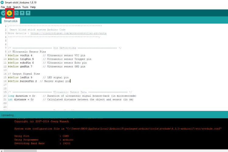
Upload code to Arduino
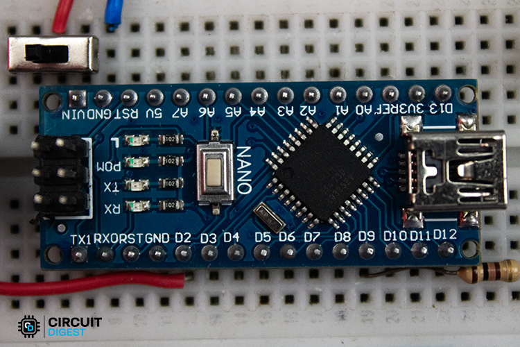
I hope you understand the logic behind the program. Ok, now it’s time to bring back the new life to our loveable Arduino by injecting binary into its memory. For that, we want to open up our Arduino IDE and make sure the Arduino Nano Board is selected properly.
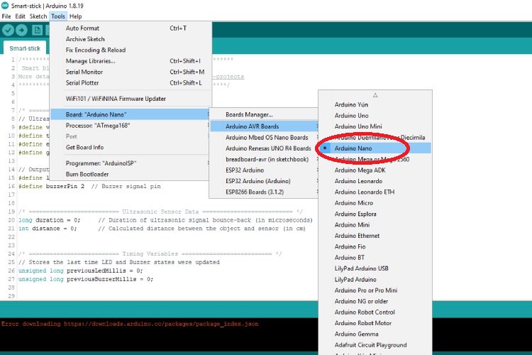
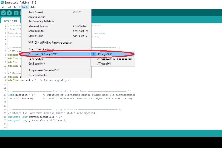
Unlike other Arduino boards, Arduino Nano comes in two different processor families, namely ATmega328p and ATmega168. In my case, Arduino Nano comes with ATmega328p processor chipset, so i choose Arduino328p.
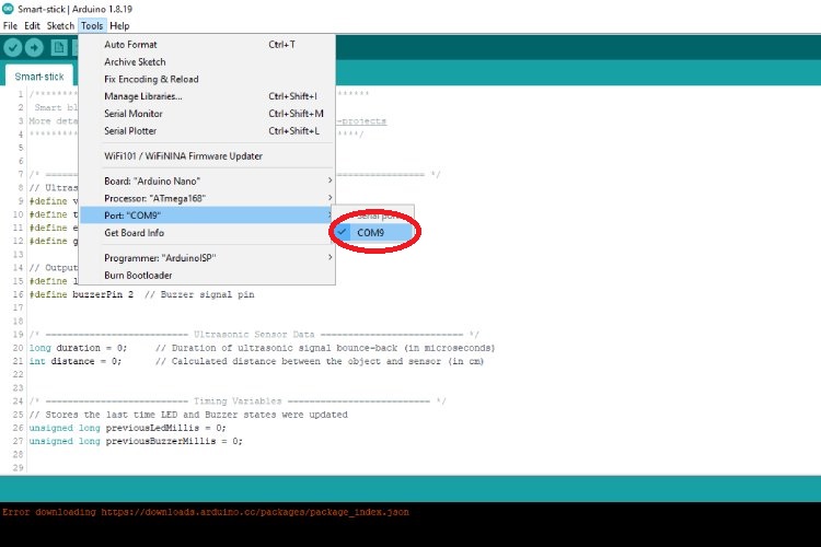
After that, we want to select the respective USB associated with our Arduino Nano.
Finally, flash the code into our Arduino Nano by clicking the upload button found on the Arduino IDE.
Ok, now the coding part is over. Now, let’s assemble our hardware in a PVC pipe to build an actual walking stick for visually impaired individuals.
Assembling Blind Stick Circuit on a PVC Pipe
In the image below, you can find how I assembled our hardware circuit in the PVC pipe. I used ZIP-Tags to attach the breadboard firmly to the PVC pipe. Here, I attached the battery to the bottom side of the breadboard using double-sided tape
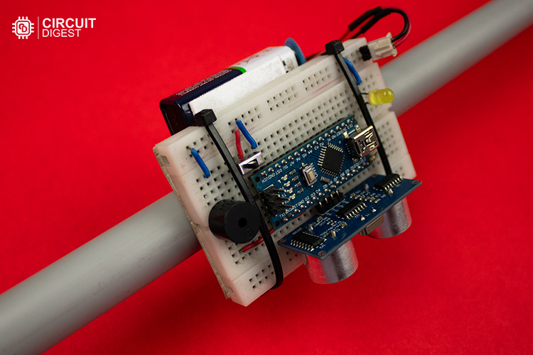
Later, I ensured that the complete breadboard setup was attached near the bottom end of the PVC Pipe so that we could detect the objects or humans before hitting them with a stick.
Final Working Demonstration
If everything went right, after turning on the Arduino Smart Stick. It starts to work perfectly, as shown in below GIF.
In the demonstration clip, you can find that this smart stick detects objects and alerts walkers through audible alerts as well as through visual alerts before hitting the obstacle. The frequency of those alerts increases when the distance from the object decreases so that walkers can get a feel of a third sense when the object is approaching them closely.
GitHub Repository with Code and Circuit
The full code for this Smart Blind Stick using Arduino project and Ultrasonic sensor is provided below. You can also access the source code in our GitHub repository through the link below.


Similar Arduino-Based Smart Blind Stick Projects
Discover a range of Arduino-based smart blind stick projects designed to assist visually impaired individuals. These projects integrate ultrasonic sensors, Arduino, Buzzers along with voice alert feedback features to enhance mobility and safety.

Voice Alert based Smart Blind Stick Using Arduino Nano and Ultrasonic Sensors
This project details the creation of a smart blind stick that uses an Arduino Nano and ultrasonic sensors to detect obstacles and provide voice alerts, enhancing navigation for visually impaired individuals.

Building a Smart Blind Stick using Arduino - Inspired by Shark Tank Torchit
Inspired by the Torchit blind stick featured on Shark Tank, this project guides you through building a similar device using an Arduino Pro Mini and ultrasonic sensors to detect obstacles and alert the user via vibrations.

Smart Blind Stick using Arduino
This project focuses on developing a smart blind stick equipped with ultrasonic sensors to detect obstacles and provide feedback through vibrations or sound, aiding visually impaired individuals in navigation.
Complete Project Code
/*************************************************************
Smart blind stick system Arduino Code
More details : https://circuitdigest.com/microcontroller-projects
************************************************************/
/* ========================== Pin Definitions ========================== */
// Ultrasonic Sensor Pins
#define vccPin 4       // Ultrasonic sensor VCC pin
#define trigPin 5      // Ultrasonic sensor Trigger pin
#define echoPin 6      // Ultrasonic sensor Echo pin
#define gndPin 7       // Ultrasonic sensor GND pin
// Output Signal Pins
#define ledPin 9       // LED signal pin
#define buzzerPin 2  // Buzzer signal pin
/* ========================== Ultrasonic Sensor Data ========================== */
long duration = 0;     // Duration of ultrasonic signal bounce-back (in microseconds)
int distance = 0;      // Calculated distance between the object and sensor (in cm)
/* ========================== Timing Variables ========================== */
// Stores the last time LED and Buzzer states were updated
unsigned long previousLedMillis = 0;
unsigned long previousBuzzerMillis = 0;
/* ========================== Multitasking Interval Variables ========================== */
// Determines the interval between LED blinks and buzzer beeps (in milliseconds)
int ledInterval = 0;        // LED blink interval — varies based on object distance
int buzzerInterval = 0;     // Buzzer beep interval — varies based on object distance
/* ========================== State Variables ========================== */
// Tracks the current state of LED and Buzzer
bool ledState = LOW;        // LED state (ON or OFF)
bool buzzerState = LOW;     // Buzzer state (ON or OFF)
/* ========================== Current Time Variable ========================== */
// Holds the current time in milliseconds
unsigned long currentMillis = 0;
/* ========================== Setup Function ========================== */
/**
* Initializes hardware components, configures I/O pins, and stabilizes the sensor.
*/
void setup() {
 // Configure Ultrasonic Sensor Pins
 pinMode(vccPin, OUTPUT);
 pinMode(trigPin, OUTPUT);
 pinMode(echoPin, INPUT);
 pinMode(gndPin, OUTPUT);
 // Configure Output Signal Pins
 pinMode(ledPin, OUTPUT);
 pinMode(buzzerPin, OUTPUT);
 // Power up the Ultrasonic Sensor
 digitalWrite(vccPin, HIGH);  // Provide 5V power
 digitalWrite(gndPin, LOW);   // Connect GND to 0V
 // Ensure all signals are in their default LOW state
 digitalWrite(ledPin, LOW);
 digitalWrite(buzzerPin, LOW);
 digitalWrite(trigPin, LOW);
 // Initialize Serial Monitor for debugging
 Serial.begin(9600);
 // Stabilize the ultrasonic sensor after powering up
 delay(1000);
}
/* ========================== Main Loop ========================== */
/**
* Continuously checks distance and triggers LED and buzzer alerts based on proximity.
*/
void loop() {
 // Capture the current time in milliseconds
 currentMillis = millis();
 // Measure the distance from the ultrasonic sensor
 measureDistance();
 // Activate LED and buzzer alerts if object is within 30cm range
 if (distance >= 0 && distance <= 30) {
   task_triggerBuzzer();
   task_triggerLed();
 } else {
   // Stop alerts if the object is out of range
   stopAlerts();
 }
}
/* ========================== Task: Trigger Buzzer ========================== */
/**
* Controls the buzzer beep rate based on object proximity.
* Buzzer beeps faster when the object is closer.
*/
void task_triggerBuzzer() {
 // Map the distance to a buzzer interval (30ms when close, 100ms when far)
 buzzerInterval = map(distance, 0, 30, 30, 100);
 // Toggle the buzzer state when the interval has passed
 if (currentMillis - previousBuzzerMillis >= buzzerInterval) {
   previousBuzzerMillis = currentMillis;      // Update the last buzzer time
   buzzerState = !buzzerState;                // Toggle the buzzer state
   digitalWrite(buzzerPin, buzzerState);      // Apply the new state to the pin
 }
}
/* ========================== Task: Trigger LED ========================== */
/**
* Controls the LED blink rate based on object proximity.
* LED blinks faster when the object is closer.
*/
void task_triggerLed() {
 // Map the distance to an LED interval (50ms when close, 100ms when far)
 ledInterval = map(distance, 0, 30, 50, 100);
 // Toggle the LED state when the interval has passed
 if (currentMillis - previousLedMillis >= ledInterval) {
   previousLedMillis = currentMillis;         // Update the last LED time
   ledState = !ledState;                      // Toggle the LED state
   digitalWrite(ledPin, ledState);            // Apply the new state to the pin
 }
}
/* ========================== Stop Alerts ========================== */
/**
* Deactivates the LED and buzzer when no object is within range.
*/
void stopAlerts() {
 digitalWrite(buzzerPin, LOW);                // Turn off the buzzer
 digitalWrite(ledPin, LOW);                   // Turn off the LED
 ledState = LOW;                              // Reset LED state
 buzzerState = LOW;                           // Reset buzzer state
}
/* ========================== Measure Distance ========================== */
/**
* Triggers the ultrasonic sensor and calculates the distance to the nearest object.
*/
void measureDistance() {
 // Send a 10µs pulse to the trigger pin to start the measurement
 digitalWrite(trigPin, LOW);
 delayMicroseconds(2);
 digitalWrite(trigPin, HIGH);
 delayMicroseconds(10);
 digitalWrite(trigPin, LOW);
 // Measure the duration of the pulse on the echo pin
 duration = pulseIn(echoPin, HIGH);
 // Calculate the distance in centimeters (speed of sound: 343 m/s)
 distance = (duration / 2) / 29.1;
 // Output the distance measurement to the Serial Monitor
 Serial.print("Distance: ");
 Serial.print(distance);
 Serial.println(" cm");
}